DATAMATH CALCULATOR MUSEUM
|
|
DATAMATH CALCULATOR MUSEUM |
Additional Pictures
| Observed signals on the
CR1 (top) and SR1 (bottom) pins of the µPD274C
clock oscillator. DUT: µPD274C H4X016 @ VDD = -6.0 V, VGG = -11.0 V, REXT1 = 150 kOhm, REXT2 = 300 kOhm, CEXT1,2 = 100 pF. 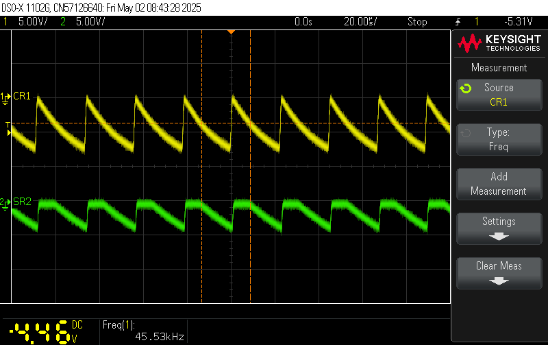 |
| Observed signals on the
CR1 (top) and
SR1 (bottom) pins of the µPD274C clock oscillator. DUT: µPD274C H4X016 @ VDD = -6.0 V, VGG = -11.0 V, REXT1 = 200 kOhm, REXT2 = 400 kOhm, CEXT1,2 = 100 pF. 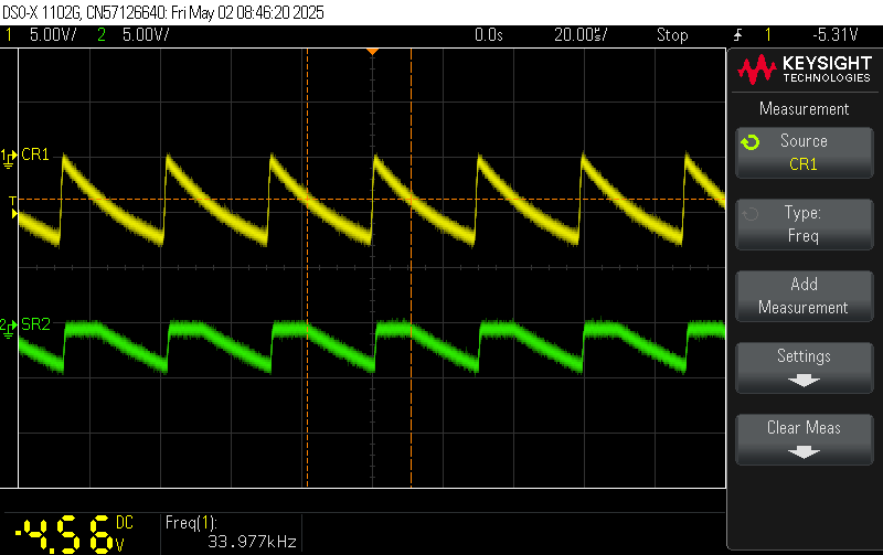 |
| Observed signals on the
CR1 (top) and
SR1 (bottom) pins of the µPD274C clock oscillator. DUT: µPD274C H4X016 @ VDD = -6.0 V, VGG = -11.0 V, REXT1 = 100 kOhm, REXT2 = 200 kOhm, CEXT1,2 = 100 pF. 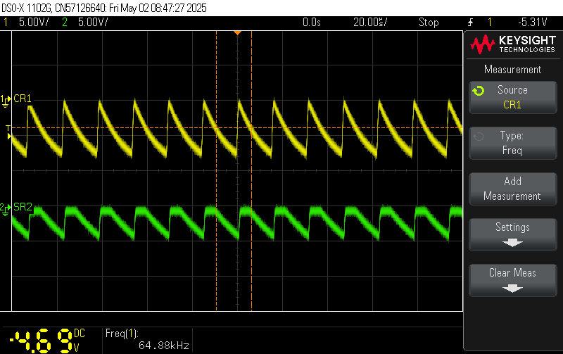 |
| Clock Frequency vs VDD Supply Voltage
of a µPD274 Series single-chip calculator circuit. DUT: µPD274C H4X016 @ VGG = -11.0 V, REXT1 = 150 kOhm, REXT2 = 300 kOhm, CEXT1,2 = 100 pF. 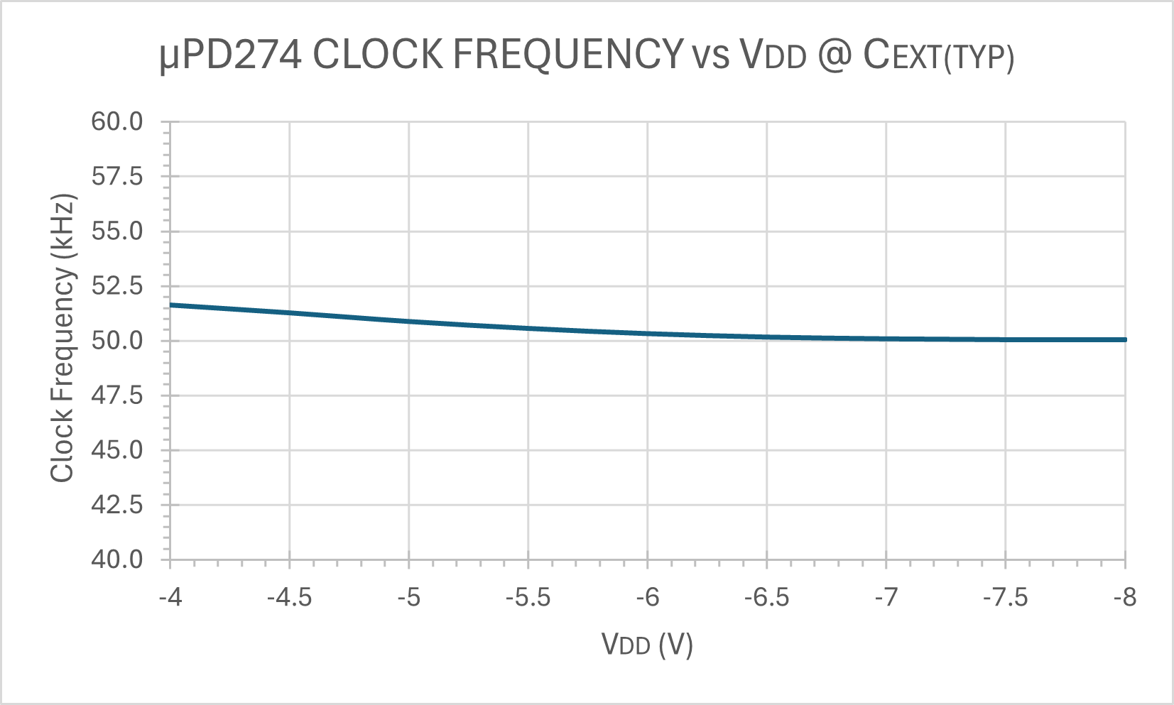 |
| Clock Frequency vs VGG Supply Voltage
of a µPD274 single-chip calculator circuit. DUT: µPD274C H4X016 @ VDD = -6.0 V, REXT1 = 150 kOhm, REXT2 = 300 kOhm, CEXT1,2 = 100 pF. 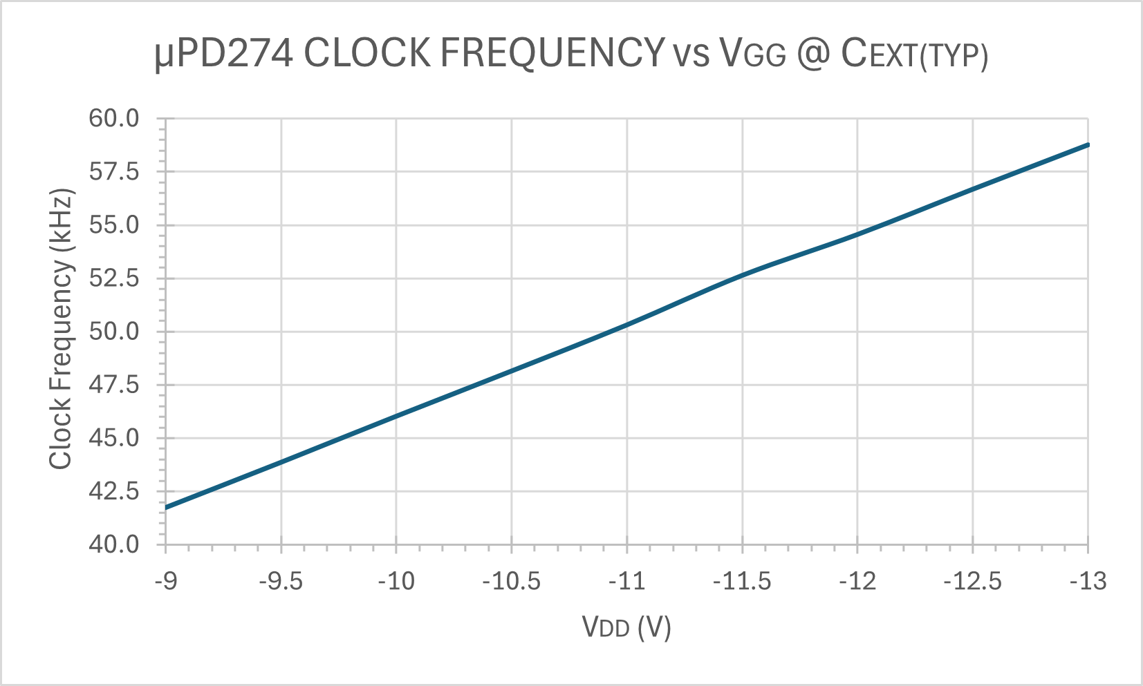 |
If you have additions to the above article please email: joerg@datamath.org.
©