DATAMATH CALCULATOR MUSEUM
|
DATAMATH CALCULATOR MUSEUM |
Texas Instruments announced on September 17, 1971 with the TMS1802NC the first available standard calculator building block on a chip, it was later renamed into TMS0102. The chip integrates 3,520 Bits Read-Only program Memory (ROM, 320 Words x 11 Bits), a 182-bit Serial-Access Memory (SAM, 3 Registers * 13 Digits, 2 * 13 Bit-Flags) and a decimal arithmetic logic unit as well as control, timing, and output decoders but no drivers for the display. These function blocks of the chip add up to an overall complexity of roughly 5,000 transistors.
Most handheld calculators built around the TMS0100 make use of 7-segment LED displays. To simplify the interface and to reduce the component count, Texas Instruments designed two special integrated circuits that allow direct interface between the TMS0100 and the TIL360, a multi-digit display.
The circuits are designated SN75491 (segment driver) and SN75492 (digit driver). They meet the driving requirements of multiplexed, common-cathode displays and include the necessary pull-down resistors for the TMS0100 outputs.
The SN75491 segment driver contains four stages, each in a Darlington configuration. Two SN75491 circuits will be employed for a calculator using the TMS0102.
QUICK-LINK to Display Drivers.
TI-2500 and other early LED calculators
| Item | Min | Typ | Max | Unit | Comments |
| VSS | 6.6 | 7.2 | 9.0 | V | |
| IL | 50 | mA | VI=6.5 V, VO=3.5 V | ||
| IL | 0.1 | mA | II=40 uA | ||
| VI-VD | 10 | V | SN75491A = 20 V |
The SN75491 was manufactured in a 10 um metal gate Bipolar process (metal width = 0.4 mil / 10 um, metal spacing = 0.4 mil / 10 um).
The die size of the SN75491 is approximately 50 mils * 35 mils / 1.3 mm * 0.9 mm.
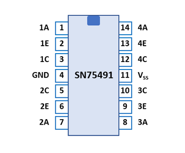
The SN75491 uses a standard 0.3” wide 14-pin DIP (Dual In-line Package with a 0.1” / 2.54 mm lead pitch).
| Pin | IO | Function | Pin | IO | Function |
| 1 | I | Segment input 1 | 14 | I | Segment input 4 |
| 2 | O | Segment output 1 | 13 | O | Segment output 4 |
| 3 | V | Collector 1 | 12 | V | Collector 4 |
| 4 | V | GND | 11 | V | VSS |
| 5 | V | Collector 2 | 10 | V | Collector 3 |
| 6 | O | Segment output 2 | 9 | O | Segment output 3 |
| 7 | I | Segment input 2 | 8 | I | Segment input 3 |
If you have additions to the above datasheet please email: joerg@datamath.org.
© Joerg Woerner, February 02, 2001. No reprints
without written permission.