DATAMATH CALCULATOR MUSEUM
|
DATAMATH CALCULATOR MUSEUM |
Texas Instruments introduced in 1978 the 2nd Generation of its wildly successful Little Professor, an educational toy very similar to a basic calculator but having the user answer computer-generated math questions. Compared to the 1st Generation of the Little Professor introduced in 1976 and based on the TMS0970 single-chip calculator family, replaced its successor based on a TMC1993 chip the power switch with a set of [ON] and [OFF] keys known already from the TI-30 calculator centered around the more capable TMC0980. The TMC1990 design exhibits an unconventional approach of scanning the keyboard switch-matrix with 10 dedicated pins (6 row outputs, 4 column inputs) instead of using either the digit-driver outputs or segment-driver outputs for the keyboard rows. While spending 6 extra pins for this purpose sounds counterproductive with respect to cost savings, did it actually reduce the complexity of the printed circuit board (PCB) dramatically by reducing cross-points in the layout between keyboard, single-chip calculator circuit, display, and battery and allowing for single-sided PCBs without using jumper wires.
From a technical point of view the TMC1990 is closely related to the TMS0970 and maintains the TMS1000 architecture with 8,192 Bits Read-Only Memory (ROM, 1k*8 Bits) and 256 Bits Random-Access Memory (RAM, 4*16 Digits), a 4-bit Arithmetic unit, a programmable PLA for segment decoding and both integrated segment and digit drivers for an 8-digit LED Display. Main differences are:
|
• Integrated power latch and power transistor for [ON] and [OFF] keys • Six of the eight State Time Signals used for segment scanning bonded on dedicated pins for keyboard scanning • Package options with Die-up (standard pinout) or Die-down (reverse pinout) options |
While the TMC1990 was introduced too late to be successful in electronic handheld calculators, proofed it to be very successful with the Little Professor manufactured between 1978 and 1982.
QUICK-LINK to Calculator Circuits with LED Direct-Drive.
| Type | Calculator/Product | Application | Comments |
| TMC1991 | TI-1000 (1977), Western Auto Citation | Basic | Die-up, Rigid-PCB |
| TMC1992 | TI-1000 (1978) | Basic | Die-down, Flex-PCB |
| TMC1993 | Little Professor (1978, early) | Educational | Die-down, Flex-PCB |
| TMC1993 |
Little Professor (1978, later), Little Professor (1980) |
Educational | Die-up, Rigid-PCB |
| Description | Comments | |
| Architecture | Single-chip Calculator | Basic, Educational |
| Category | Digit Processor | 4-bit Digits |
| Related | TMS1000 Portfolio | |
| ROM Size | 8,192 Bits | 1024 Words * 8 Bits |
| RAM Size | 256 Bits | 64 Digits |
| Outputs | 8 Digits, 8 Segments, 6 Keyboard | Internal Digit and Segment Drivers, State Time STA - STE, STG |
| Inputs | 4 Keyboard | State Time (Segments) to Keyboard Scan-Matrix |
| Item | Min | Typ | Max | Unit | Comments |
| VSS | 0 | V | |||
| VDD | -9.0 | V | |||
| CK | 150 | 250 | 333 | kHz | Internal oscillator |
The TMC1990 was manufactured in a 6 um metal gate PMOS process (metal width = 0.25 mil / 6.0 um, metal spacing = 0.25 mil / 6.0 um, diffusion width = 0.20 mil / 5.0 um, diffusion spacing = 0.25 mil / 6.0 um).
The die size of the TMC1990 is approximately 160 mils * 125 mils / 4.0 mm * 3.1 mm.
The TMC1990 uses a 0.4” wide 28-pin SPDIP (Shrink Plastic Dual In-line Package with a 0.07” / 1.778 mm lead pitch) with standard (Die-up) or reverse (Die-down) pinout.
TMC1990 (Die-up)
| Pin | IO | Function | Pin | IO | Function |
| 1 | O | Digit driver 4 | 28 | O | Digit driver 3 |
| 2 | O | Digit driver 5 | 27 | O | Digit driver 2 |
| 3 | O | Digit driver 6 | 26 | O | Digit driver 1 (LSD) |
| 4 | O | Digit driver 7 | 25 | O | Segment driver DP |
| 5 | O | Digit driver 8 (sign/MSD) | 24 | O | Segment driver C |
| 6 | O | State Time A | 23 | O | Segment driver D |
| 7 | O | State Time B | 22 | O | Segment driver E |
| 8 | I | Keymatrix input 1 | 21 | O | Segment driver F |
| 9 | O | State Time C | 20 | O | Segment driver G |
| 10 | I | Keymatrix input 2 | 19 | O | Segment driver A |
| 11 | O | State Time D | 18 | O | Segment driver B |
| 12 | I | Keymatrix input 3 | 17 | V | Negative Voltage VDD |
| 13 | O | State Time E | 16 | V | Positive Voltage VSS |
| 14 | I | Keymatrix input 4 | 15 | O | State Time G |
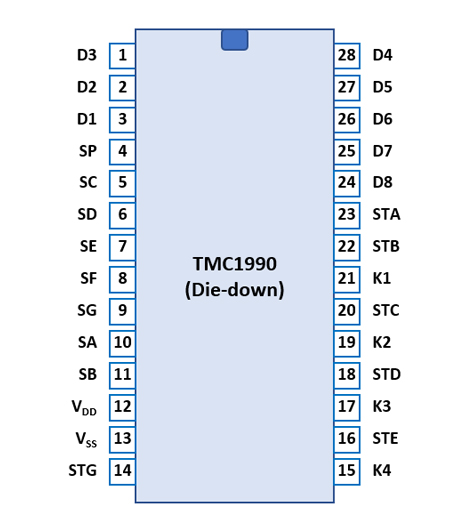 TMC1990
(Die-down)
TMC1990
(Die-down)| Pin | IO | Function | Pin | IO | Function |
| 1 | O | Digit driver 3 | 28 | O | Digit driver 4 |
| 2 | O | Digit driver 2 | 27 | O | Digit driver 5 |
| 3 | O | Digit driver 1 (rightmost) | 26 | O | Digit driver 6 |
| 4 | O | Segment driver DP | 25 | O | Digit driver 7 |
| 5 | O | Segment driver C | 24 | O | Digit driver 8 (leftmost) |
| 6 | O | Segment driver D | 23 | O | State Time A |
| 7 | O | Segment driver E | 22 | O | State Time B |
| 8 | O | Segment driver F | 21 | I | Keymatrix input 1 |
| 9 | O | Segment driver G | 20 | O | State Time C |
| 10 | O | Segment driver A | 19 | I | Keymatrix input 2 |
| 11 | O | Segment driver B | 18 | O | State Time D |
| 12 | V | Negative Voltage VDD | 17 | I | Keymatrix input 3 |
| 13 | V | Positive Voltage VSS | 16 | O | State Time E |
| 14 | O | State Time G | 15 | I | Keymatrix input 4 |
| The Segment drivers A-G and DP (Decimal Point) are connected to the display in the pictured way. | 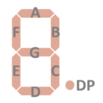 |
The keyboards of all calculators based on the TMC1990 Product Family consist of a x/y-matrix connected to up to six State Time outputs STA, STB, STC, STD, STE, and STG (segments) and the keymatrix inputs K1, K2, K3, and K4.
Example for the TI-1000 with TMC1991, TMC1992:
| K1 | K2 | K3 | K4 | |
| STG | OFF | +/− | % | ÷ |
| STE | 7 | 8 | 9 | × |
| STD | 4 | 5 | 6 | − |
| STC | 1 | 2 | 3 | + |
| STA | ON CE/C |
O | . | = |
Example for the
Little Professor with TMC1993:
| K1 | K2 | K3 | K4 | |
| STG | OFF | SET | LEVEL | |
| STE | 7 | 8 | 9 | ÷ |
| STD | 4 | 5 | 6 | × |
| STC | 1 | 2 | 3 | − |
| STA | ON | O | GO | + |
Calculators based on the based on the TMC1990 make use of 8-digit LED Displays with common cathode architecture.
If you have additions to the above datasheet please email: joerg@datamath.org.
© Sean Riddle and Joerg Woerner, April 20, 2021. No reprints
without written permission.