DATAMATH CALCULATOR MUSEUM
|
DATAMATH CALCULATOR MUSEUM |
With the TMS1802NC Texas Instruments announced on September 17, 1971 the first available standard calculator building block on a chip, it was later renamed into TMS0102. The chip integrates 3520-bit Read-Only program memory, a 182-bit Serial-Access memory and a decimal arithmetic logic unit as well as control, timing, and output decoders but no drivers for the display. This gives an overall complexity of roughly 5,000 transistors.
Gordon Moore, the co-founder of Fairchild Semiconductor and Intel predicted already in 1965 that the numbers of transistors in Large-scale Integration (LSI) chips would double every year for the next 10 years. In 1975, looking forward to the next decade, he revised the forecast to doubling every two years, a compound annual growth rate (CAGR) of 41%. While Moore did not use empirical evidence in forecasting that the historical trend would continue, his prediction held since 1975 and has since become known as a "law". Main enablers were and are a combination of both reducing the size of the individual components (process shrink) and increasing the chip size (yield improvement). The manufacturing costs of an Integrated Circuit (IC) are calculated with:
|
• IC cost = (Die cost + Testing cost + Packaging cost) / Final test yield |
 With the die cost roughly proportional to the die area, testing and packaging costs roughly proportional to the pin count, and the final test yield mostly inverse proportional to the die area, goals are well defined: Keep the die size as small as possible for a set of requirements agreed on. With both ROM (Read-Only Memory) and RWM (Read-Write Memory) sizes the main contributors to the die area
of a single-chip calculator circuit and shift-register based data memory (SAM,
Serial-Access Memory) of Register Processors denser than RAM (Random-Access Memory) of Digit Processors, Texas Instruments
expanded the TMS0100 Product Family two years after its introduction into three
different branches:
With the die cost roughly proportional to the die area, testing and packaging costs roughly proportional to the pin count, and the final test yield mostly inverse proportional to the die area, goals are well defined: Keep the die size as small as possible for a set of requirements agreed on. With both ROM (Read-Only Memory) and RWM (Read-Write Memory) sizes the main contributors to the die area
of a single-chip calculator circuit and shift-register based data memory (SAM,
Serial-Access Memory) of Register Processors denser than RAM (Random-Access Memory) of Digit Processors, Texas Instruments
expanded the TMS0100 Product Family two years after its introduction into three
different branches:
|
• TMS0600: Increased ROM (384 Words
* 11 Bits), Identical SAM (13 Digits Registers), external display drivers. Process shrink, higher functionality • TMS0700: Identical ROM (320 Words * 11 Bits), Identical SAM (13 Digits Registers), external display drivers. Process shrink, identical functionality, cost reduction of IC • TMS0800: Identical ROM (320 Words *11 Bits), Reduced SAM (11 Digits Registers), integrated segment drivers. Process shrink, reduced functionality, higher integration |
Please notice that the members of the TMS0700 family were still marketed and marked as TMS0100 but both the die and the bottom of the chip package usually sport a TMS0700 marking.
While the TMS0600 architecture was based on the flexible design concept of the TMS0100 architecture with both programmable PLA and ROM techniques, only few design variations appeared. The first two designs of the small TMS0600 Product Family labeled TMS0601 and TMS0602 were just algorithm enhancements of existing designs labeled TMS0119 and TMS0120, respectively:
| Features/ Device |
[0]...[9] [.] |
[+] [−] [×] [÷] [=] |
[+/−] | [C] [CE] | [CONST] | [F/2/4] | [%] | [Memory] | [EE] | [1/x] | [x2] | [√x] | [PI] | Display Format |
| TMS0119 | * | * | * | * | * | E88888888 | ||||||||
| TMS0601 | * | * | * | * | * | * | * | E88888888 | ||||||
| TMS0120 | * | * | * | * | * | * | * | * | E88888888-88 | |||||
| TMS0602 | * | * | * | * | * | * | * | * | * | * | E88888888-88 |
| Type | Calculators | Keyboard | Constant (M-D-A-S) |
Digits | Fixed DP | Rounding | Special Functions |
Seg./Dig. Blanking |
(6,7,9) Font |
Seg. H | Memory | Entry Overflow |
Calculating Overflow |
Memory Overflow |
| TMC0601 TMS0601 |
TI-2550 | [+]−][=] | 1-2-1-2 | 8 | 0-7, F | 5/4 |
[M+][M−][MR][MC] [%] |
NONE NONE |
||||||
| TMS0602 | SR-11 | [+][−][=] | [ - K] 1-2-X-X |
8+2 | Float | NONE | [EE][+/−][1/x] [x2][√x][PI] |
NONE NONE |
||||||
| TMS0603 | Brother 827R (Version 2), Kovac LE-808M | [+]−][=] | 1-2-2-2 | 8 | Float | NONE |
[M+][M−][MR][MC] [%][1/x][x2] [X<>Y][X<>M] |
S1, S13 S1, S13 |
Memory (D8) Others |
Seg. H(D8) | ||||
| TMS0604 | Dittel TMP608, Helec GT 539 | [+=][−=] | [ - K] 1-2-X-X |
8 | Float | NONE | [M+=][M−=][S] [T][CM][ - ∑] [%] |
S1, S13 S1, S13 |
Memory (D8) Others |
Seg. H(D8) | ||||
| TMC0605 | Canon LE-81M | [+][−][=] | 1-2-X-X | 8 | Float | NONE | [T][ - ∑] [%±][√x] |
NONE S1, S13 |
Memory (D8) Others |
Seg. H(D8) | ||||
| TMS0611 | Craig 4518, Kovac LE-808MR | [+][−][=] | 1-2-X-X | 8 | Float | NONE | [M+][M−][T] [%±][√x] |
S1, S13 S1, S13 |
| Description | Comments | |
| Architecture | Single-chip Calculator | First Generation |
| Category | Register Processor | BCD-serial |
| Related |
TMS0700 TMS0800 |
Die-shrink Integrated Segment Drivers |
| ROM Size | 4,224 Bits | 384 Words * 11 Bits |
| RAM Size | 182 Bits | 3 Registers * 13 Digits, 2 * 13 Bit-Flags |
| Outputs | 11 Digits 9 Segments |
External Digit Drivers External Segment Drivers |
| Inputs | 4 Keyboard 0 Miscellaneous |
Digit to Keyboard Scan-Matrix |
Capacity: Up to 8 digits (positive and negative)
Logic: Algebraic Chain Logic with Automatic Constant
[2] [x] [3] [+] [4] [x] [5] [=] → '50.'
Number Entry: Right-justified number entry, entering a ninth digit is ignored
[1] [2] [3] [4] [5] [6] [7] [8] [9] → '12345678.'
Decimal Point: First entered decimal point is used, additional decimal point entries are ignored
[1] [.] [2] [.] [3] → '1.23'
Fixed Decimal Point: The decimal point can be set to [0 1 2 3 4 5 6 7 F] digits
[0 1 2 3 4 5 6 7 F]: [1] [+=] [2] [+=] → '3.000'
Clear: Automatic power-up clear implemented. [C] key clears the whole calculator but the memory, [CE] key clears last entry of a number
[1] [+] [2] [C] [3] [=] → '3.'; [1] [+] [2] [CE] [3] [=] → '4.'
Change Sign: Not supported. When performing multiplication or division, a negative value can be assigned by pressing the [−] key before entering the number
[−] [2] [x] [3] [=] → '- 6.'; [−] [2] [x] [−] [3] [=] → '6.'
Number Display: Right-justified number display with leading-zero suppression
Negative Numbers: Negative numbers are shown with '-' at leftmost display position D11
Calculating Overflow: An overflow shows the result with the decimal point shifted 8 positions to the left and 'u' (or 'o' for negative numbers) in the leftmost position and is only recoverable with the [C] key
[1] [2] [3] [4] [5] [x] [1] [2] [3] [4] [5] [=] → 'u1.5239902'
Memory: 4-key memory with [M+], [M−], [MR] and [CM] keys implemented. Memory store is indicated with 'upper n' in the leftmost position
[CM] [3] [x] [2] [M+] → 'upper n 2.', [=] → 'upper n 6.', [C] → 'upper n 0.', [MR] → 'upper n 2.', [CM] → '2.'
Memory Overflow: A memory overflow keeps the displayed value in place and is indicated with '0.' (or '8' for negative numbers) in the leftmost position. It is only recoverable using the [CM] key
[CM] [9] [9] [9] [9] [9] [9] [9] [8] [M+] → 'upper n 99999998.', [3] [M+] → '0 3.', [C] → '0 3.', [CM] → '3.'
Divide By Zero: A division of a positive or negative number by zero shows a '0' and 'u' in the leftmost position and is only recoverable using the [C] key
[1] [:] [0] [=] → 'u 0.'; [−] [1] [:] [0] [=] → 'u 0.'
Timeout: Not supported
Rounding: Rounding of displayed calculating results is supported in Fixed decimal Point Mode
[0 1 2 3 4 5 6 7 F]: [2] [0] [:] [3] [=] → '6.667'
Automatic Constant: Implemented for multiplication (1st number used as constant), division (2nd), addition (1st), and subtraction (2nd)
[3] [x] [2] [=] [=] → '18.', [1] [=] → '3.'; [4] [x] [=] [=] → '64.'
[3] [:] [2] [=] [=] → '0.75', [1] [=] → '0.5.'; [4] [:] [=] [=] → '0.25'
[3] [+] [2] [=] [=] → '8.', [1] [=] → '4.'; [4] [+] [=] [=] → '12.'
[3] [−] [2] [=] [=] → '- 1.', [1] [=] → '- 1.'; [4] [−] [=] [=] → '- 4.'
Percent Function: The [%] key followed by the [x] key allows with the [+] and [−] keys mark-up and discount calculations. Using the [=] key following the [%] key in multiplication leads to unexpected results
[2] [0] [x] [5] [%] → '1.', [=] → '20.'
[2] [0] [x] [5] [%] → '1.', [+] → '21.', [=] → '420.'
[2] [0] [x] [5] [%] → '1.', [−] → '19.', [=] → '380.'
[5] [:] [2] [0] [%] → '0.2', [=] → '25.'
Known Calculator Logic Bugs: None
Capacity: Up to 8 digits (positive and negative) for mantissa and up 2 digits (positive and negative) for exponent
Logic: Algebraic Chain Logic with Constant
[2] [x] [3] [+] [4] [x] [5] [=] → '50.'
Number Entry: Right-justified number entry, entering a ninth digit is ignored
[1] [2] [3] [4] [5] [6] [7] [8] [9] → '12345678'
Decimal Point: First entered decimal point is used, additional decimal point entries are ignored
[1] [.] [2] [.] [3] → '1.23'
Fixed Decimal Point: Fixed decimal point arithmetic is not supported
Clear: Automatic power-up clear implemented. [C] key clears the whole calculator, [CD] key clears last entry of a number
[1] [+] [2] [C] [3] [=] → '3.'; [1] [+] [2] [CD] [3] [=] → '4.'
Change Sign: The change sign function can be used anytime for the mantissa before [EE] is pressed. Then it toggles the sign of the exponent
[+/−] [2] [x] [3] [+/−] [=] → '6.'; [2] [+/−] [EE] [3] [+/−] → '- 2 -03'
Number Display: Right-justified number display with leading-zero suppression
Negative Numbers: Negative numbers are shown with '-' for mantissa and Segment H for exponent at leftmost display position D11
Calculating Overflow: An overflow shows the result with the exponent shifted by 100 and 'C' (or 'E' for negative numbers) in the leftmost position and is recoverable with the [C] key
[1] [.] [2] [3] [4] [5] [EE] [5] [0] [x] [1] [.] [2] [3] [4] [5] [EE] [6] [0] [=] → 'C1.5239902 10', [C] → '0'
Divide By Zero: A division of a positive or negative number by zero shows a 'C' and is recoverable with the [C] key
[1] [:] [0] [=] → 'C 0.'; [+/−] [1] [:] [0] [=] → 'C 0.', [C] → '0'
Timeout: Not supported
Rounding: Rounding of displayed calculating results is not supported
[2] [0] [:] [3] [=] → '6.6666666'
Constant: Automatic constant can be enabled with an external switch and is implemented for multiplication (1st number used as constant) and division (2nd)
[- K] [3] [x] [2] [=] [=] → '6.', [1] [=] → '1.'; [4] [x] [=] [=] → '16.'
[- K] [3] [x] [2] [=] [=] → '18.', [1] [=] → '3.'; [4] [x] [=] [=] → '64.'
[- K] [3] [:] [2] [=] [=] → '0.75', [1] [=] → '0.5.'; [4] [:] [=] [=] → '0.25'
Reciprocal Overflow: Calculating the reciprocal of zero shows a zero and 'C' in the leftmost position and is recoverable with the [C] key
[0] [1/x] → 'C 0.', [C] → '0'
Square Overflow: An overflow shows the result with the exponent shifted by 100 and 'C' in the leftmost position and is recoverable with the [C]
[1] [.] [2] [3] [4] [5] [EE] [5] [5] [x2] → 'C1.5239902 10', [C] → '0
Negative Square Root: Negative square roots are not allowed and result in an overflow condition indicated with an 'E' in the leftmost position and is recoverable with the [C] key
[8] [√x] → '2.8284271'; [+/−] [8] [√x] → 'E 2.828427'
Known Calculator Logic Bugs:
Calculator Overflow Bug: Calculator overflow is allowed and calculations can be continued by ignoring the overflow condition
[1] [.] [2] [3] [4] [5] [EE] [5] [0] [x] [1] [.] [2] [3] [4] [5] [EE] [6] [0] [=] → 'C1.5239902 10', [:] [1] [0] [=] → 'C1.5239902 08'
[1] [:] [0] [=] → 'C 0.', [+] [1] [=] → 'C
Negative Square Root Bug: Negative square roots are not allowed and result in a negative number with calculator overflow and calculations can be continued by ignoring the overflow condition
[+/−] [8] [√x] → 'E 2.8284271', [+] [1] [=] → 'E 1.8284271'
Capacity: Up to 8 digits (positive and negative)
Logic: Algebraic Chain Logic with Automatic Constant
[2] [x] [3] [+] [4] [x] [5] [=] → '50.'
Number Entry: Right-justified number entry, entering a ninth digit is ignored
[1] [2] [3] [4] [5] [6] [7] [8] [9] → '12345678.'
Decimal Point: First entered decimal point is used, additional decimal point entries are ignored
[1] [.] [2] [.] [3] → '1.23'
Fixed Decimal Point: Fixed decimal point arithmetic is not supported
Decimal Alignment: Decimal alignment is supported for additions and subtractions
[0] [.] [4] [5] [+] [0] [.] [5] [5] [=] → '1.00'
Clear: Automatic power-up clear implemented. [CA] key clears the whole calculator. First press of the [C/CE] key clears last entry of a number, second press clears the calculator but the memory
[1] [+] [2] [C/CE] [3] [=] → '4.'; [1] [+] [2] [C/CE] [C/CE] [3] [=] → '3.'
Change Sign: Not supported. When performing multiplication or division, a negative value can be assigned by pressing the [−] key before entering the number
[−] [2] [x] [3] [=] → '- 6.'; [−] [2] [x] [−] [3] [=] → '6.'
Number Display: Right-justified number display with leading-zero suppression
Negative Numbers: Negative numbers are shown with '-' at leftmost display position D11
Calculating Overflow: An overflow shows the result with the decimal point shifted 8 positions to the left and 'C' (or 'E' for negative numbers) in the leftmost position and is only recoverable with the [C/CE] or [CA] keys
[1] [2] [3] [4] [5] [x] [1] [2] [3] [4] [5] [=] → 'C1.5239902'
Memory: 5-key memory with [M+], [M−], [MR], [CM] and [X<>M] keys implemented. Memory store is indicated with 'Segment H' in the position D8 (H8)
[CM] [3] [x] [2] [M+] → 'H8 2.', [=] → 'H8 6.', [C] → 'H8 0.', [MR] → 'H8 2.', [CM] → '2.'
Auto-Summation: Auto-Summation can be enabled with an external switch and adds with each press of the [=] key the display result to the value already stored in the memory Memory store is indicated with '.' in the leftmost position
[ - ∑] [CM] [3] [x] [2] [=] → 'H8 6.', [=] → 'H8 18.', [MR] → 'H8 24.'
Memory Overflow: A memory overflow is indicated with an 'upper n' in the leftmost position. It is recoverable using the [CA], [C/CE] or [CM] keys
[CM] [9] [9] [9] [9] [9] [9] [9] [8] [M+] → 'H8 99999998.', [3] [M+] → 'upper n 3.', [C/CE] → 'upper n 0.', [CM] → '0.'
Divide By Zero: A division of a positive or negative number by zero shows a 'C' in the leftmost position and is only recoverable using the [CA] or [C/CE] keys
[1] [:] [0] [=] → 'C 0.'; [−] [1] [:] [0] [=] → 'C 0.'
Timeout: Not supported
Rounding: Rounding of displayed calculating results is not supported
[2] [0] [:] [3] [=] → '6.6666666'
Automatic Constant: Implemented for multiplication (1st number used as constant), division (2nd), addition (2nd), and subtraction (2nd)
[3] [x] [2] [=] [=] → '18.', [1] [=] → '3.'; [4] [x] [=] [=] → '64.'
[3] [:] [2] [=] [=] → '0.75', [1] [=] → '0.5.'; [4] [:] [=] [=] → '0.25'
[3] [+] [2] [=] [=] → '7.', [1] [=] → '3.'; [4] [+] [=] [=] → '12.'
[3] [−] [2] [=] [=] → '- 1.', [1] [=] → '- 1.'; [4] [−] [=] [=] → '- 4.'
Percent Function: The [+] and [−] keys followed by the [%] key allows mark-up and discount calculations
[2] [0] [+] [5] [%] → '1.', [=] → '21.'
[2] [0] [-] [5] [%] → '1.', [=] → '19.'
Reciprocal Overflow: Calculating the reciprocal of zero shows a zero and 'C' in the leftmost position and is only recoverable with the [C/CE] or [CA] keys
[0] [1/x] → 'C 0.', [C/CE] → '0.'
Square Overflow: An overflow shows the result with the decimal point shifted 8 positions to the left and 'C' in the leftmost position and is only recoverable with the [C/CE] or [CA] keys
[1] [2] [3] [4] [5] [x2] → 'C1.5239902'
Register Exchange: The [X<>Y] and [X<>M] keys allow the exchange of the display register with the operand register and memory register, respectively
[1] [:] [2] → '2.', [X<>Y] → '1.', [=] → '2.'
[1] [M+] [:] [2] [X<>M] → '1.', [=] → '1.'
Known Calculator Logic Bugs:
Memory Overflow Bug: A memory overflows cleared with the [C/CE] key keeps the result with the decimal point shifted 8 positions to the left in the memory
[CM] [9] [9] [9] [9] [9] [9] [9] [8] [M+] → 'H8 99999998.', [3] [M+] → 'upper n 3.', [C/CE] → 'upper n 0.', [C/CE] → 'H8 0.', [MR] → '1.0000000.'
Capacity: Up to 8 digits (positive and negative)
Logic: Algebraic Adding Machine Logic with Constant
[2] [x] [3] [+=] [4] [x] [5] [+=] → '20.'
Number Entry: Right-justified number entry, entering a ninth digit is ignored
[1] [2] [3] [4] [5] [6] [7] [8] [9] → '12345678.'
Decimal Point: First entered decimal point is used, additional decimal point entries are ignored
[1] [.] [2] [.] [3] → '1.23'
Fixed Decimal Point: Fixed decimal point arithmetic is not supported
Decimal Alignment: Decimal alignment is not supported
[0] [.] [4] [5] [+=] [0] [.] [5] [5] [+=] → '1.'
Clear: Automatic power-up clear implemented. [CA] key clears the whole calculator. First press of the [C/CE] key clears last entry of a number, second press clears the calculator but the memory
[1] [+=] [2] [C] [3] [+=] → '4.'; [1] [+=] [2] [C] [C] [3] [+=] → '3.'
Change Sign: Not supported. When performing multiplication or division, a negative value can be assigned by pressing the [−=] key after entering the number
[2] [−=] [x] [3] [+=] → '- 6.'; [2] [−=] [x] [3] [−=] → '6.'
Number Display: Right-justified number display with leading-zero suppression
Negative Numbers: Negative numbers are shown with '-' at leftmost display position D11
Calculating Overflow: An overflow shows the result with the decimal point shifted 8 positions to the left and 'C' (or 'E' for negative numbers) in the leftmost position and is only recoverable with the [C/CE] or [CA] keys
[1] [2] [3] [4] [5] [x] [1] [2] [3] [4] [5] [+=] → 'C1.5239902'
Memory: 5-key memory with [M+=], [M−=], [S], [T] and [CM] keys implemented. Memory store is indicated with 'Segment H' in the position D8 (H8)
[CM] [3] [x] [2] [M+=] → 'H8 6.', [M+=] → 'H8 6.', [C/CE] → 'H8 0.', [S] → 'H8 12.', [C/CE] → 'H8 0.', [T] → '12.'
Auto-Summation: Auto-Summation can be enabled with an external switch and adds or subtracts with each press of the [+=] and [=] keys the display result to the value already stored in the memory. Memory store is indicated with 'Segment H' in the position D8 (H8)
[ - ∑] [CM] [3] [x] [2] [+=] → 'H8 6.', [+=] → 'H8 12.', [S] → 'H8 12.'
Memory Overflow: A memory overflow is indicated with an 'upper n' in the leftmost position. It is recoverable using the [CA], [C/CE] or [CM] keys
[CM] [9] [9] [9] [9] [9] [9] [9] [8] [M+=] → 'H8 99999998.', [3] [M+=] → 'upper n 3.', [C] → 'upper n 0.', [CM] → '0.'
Divide By Zero: A division of a positive or negative number by zero shows a 'C' in the leftmost position and is only recoverable using the [CA] or [C/CE] keys
[1] [:] [0] [+=] → 'C 0.'; [1] [−=] [:] [0] [+=] → 'C 0.'
Timeout: Not supported
Rounding: Rounding of displayed calculating results is not supported
[2] [0] [:] [3] [+=] → '6.6666666'
Constant: Automatic constant can be enabled with an external switch and is implemented for multiplication (1st number used as constant) and division (2nd)
[- K] [3] [x] [2] [+=] [+=] → '9.', [1] [+=] → '10.'; [4] [x] [+=] [+=] → '20.'
[- K] [3] [x] [2] [+=] [+=] → '18.', [1] [+=] → '3.'; [4] [x] [+=] [+=] → '64.'
[- K] [3] [:] [2] [+=] [+=] → '0.75', [1] [+=] → '0.5.'; [4] [:] [+=] [+=] → '0.25'
Percent Function: The [%] key followed the [x] or [:] keys allows with the [+=] and [−=] keys mark-up and discount calculations
[2] [0] [x] [5] [%] → '1.', [+=] → '21.'
[2] [0] [x] [5] [%] → '1.', [−=] → '19.'
[2] [0] [:] [5] [%] → '5.', [+=] → '21.052631'
[2] [0] [:] [5] [%] → '5.', [−=] → '19.047619'
Known Calculator Logic Bugs:
Memory Overflow Bug: A memory overflows not cleared or cleared with the [C/CE] key keeps the result with the decimal point shifted 8 positions to the left in the memory
[CM] [9] [9] [9] [9] [9] [9] [9] [8] [M+=] → 'H8 99999998.', [3] [M+=] → 'upper n 3.', [C/CE] → 'upper n 0.', [T] → '1.0000000.'
Capacity: Up to 8 digits (positive and negative)
Logic: Algebraic Chain Logic with Automatic Constant
[2] [x] [3] [+] [4] [x] [5] [=] → '50.'
Number Entry: Right-justified number entry, entering a ninth digit is ignored
[1] [2] [3] [4] [5] [6] [7] [8] [9] → '12345678.'
Decimal Point: First entered decimal point is used, additional decimal point entries are ignored
[1] [.] [2] [.] [3] → '1.23'
Fixed Decimal Point: Fixed decimal point arithmetic is not supported
Decimal Alignment: Decimal alignment is not supported
[0] [.] [4] [5] [+] [0] [.] [5] [5] [=] → '1.'
Clear: Automatic power-up clear implemented. [C] key clears the whole calculator, [CE] key clears last entry of a number
[1] [+] [2] [C] [3] [=] → '3.'; [1] [+] [2] [CE] [3] [=] → '4.'
Change Sign: Not supported. When performing multiplication or division, a negative value can be assigned by pressing the [−] key before entering the number
[−] [2] [x] [3] [=] → '- 6.'; [−] [2] [x] [−] [3] [=] → '6.'
Number Display: Right-justified number display with leading-zero suppression
Negative Numbers: Negative numbers are shown with '-' at leftmost display position D11
Calculating Overflow: An overflow shows the result with the decimal point shifted 8 positions to the left and 'C' (or 'E' for negative numbers) in the leftmost position and is only recoverable with the [C] key
[1] [2] [3] [4] [5] [x] [1] [2] [3] [4] [5] [=] → 'C1.5239902'
Memory: 1-key memory with [ - AM] switch and [T] key implemented. Memory store is indicated with 'Segment H' in the position D8 (H8)
Auto-Summation: Auto-Summation can be enabled with an external switch and adds with each press of the [=] key after a calculation the display result to the value already stored in the memory Memory store is indicated with '.' in the leftmost position
[ - AM] [T] [3] [x] [2] [=] → 'H8 6.', [=] → 'H8 18.', [T] → '24.'
Memory Overflow: A memory overflow is indicated with a 'C' (or 'E' for negative numbers) in the leftmost position. It is only recoverable using the [C] key
[T] [9] [9] [9] [9] [9] [9] [9] [8] [x] [1] [=] → 'H8 99999998.', [3] [x] [1] [=] → 'C3.0000000', [C] → 'H8 0.'
Divide By Zero: A division of a number by zero shows a 'C' (or 'E' for negative numbers) in the leftmost position and is only recoverable using the [C] key
[1] [:] [0] [=] → 'C 0.'; [−] [1] [:] [0] [=] → 'E 0.'
Timeout: Not supported
Rounding: Rounding of displayed calculating results is not supported
[2] [0] [:] [3] [=] → '6.6666666'
Automatic Constant: Implemented for multiplication (1st number used as constant) and division (2nd)
[3] [x] [2] [=] [=] → '18.', [1] [=] → '3.'; [4] [x] [=] [=] → '64.'
[3] [:] [2] [=] [=] → '0.75', [1] [=] → '0.5.'; [4] [:] [=] [=] → '0.25'
[3] [+] [2] [=] [=] → '5.', [1] [=] → '1.'; [4] [+] [=] [=] → '4.'
[3] [−] [2] [=] [=] → '1.', [1] [=] → '1.'; [4] [−] [=] [=] → '4.'
Negative Square Root: Negative square roots are not allowed and result in an overflow condition indicated with an 'E' in the leftmost position and is only recoverable with the [C] key
[8] [√x] → '2.828427'; [−] [8] [√x] → 'E 2.828427'
Percent Function: The [%±] is implemented for addition and subtraction for add-on and discount calculations
[2] [0] [x] [5] [%±] → '1.', [+] [=] → '21.'
[2] [0] [x] [5] [%±] → '1.', [−] [=] → '19.'
Known Calculator Logic Bugs:
Memory Overflow Bug: A memory overflows cleared with the [C] key keeps the result with the decimal point shifted 8 positions to the left in the memory
[T] [9] [9] [9] [9] [9] [9] [9] [8] [x] [1] [=] → 'H8 99999998.', [3] [x] [1] [=] → 'C3.0000000', [C] → 'H8 0.' [T] → '1.0000000.'
Capacity: Up to 8 digits (positive and negative)
Logic: Algebraic Chain Logic with Automatic Constant
[2] [x] [3] [+] [4] [x] [5] [=] → '50.'
Number Entry: Right-justified number entry, entering a ninth digit is ignored
[1] [2] [3] [4] [5] [6] [7] [8] [9] → '12345678.'
Decimal Point: First entered decimal point is used, additional decimal point entries are ignored
[1] [.] [2] [.] [3] → '1.23'
Fixed Decimal Point: Fixed decimal point arithmetic is not supported
Decimal Alignment: Decimal alignment is not supported
[0] [.] [4] [5] [+] [0] [.] [5] [5] [=] → '1.'
Clear: Automatic power-up clear implemented. [C] key clears the whole calculator, [CE] key clears last entry of a number
[1] [+] [2] [C] [3] [=] → '3.'; [1] [+] [2] [CE] [3] [=] → '4.'
Change Sign: Not supported. When performing multiplication or division, a negative value can be assigned by pressing the [−] key before entering the number
[−] [2] [x] [3] [=] → '- 6.'; [−] [2] [x] [−] [3] [=] → '6.'
Number Display: Right-justified number display with leading-zero suppression
Negative Numbers: Negative numbers are shown with '-' at leftmost display position D11
Calculating Overflow: An overflow shows the result with the decimal point shifted 8 positions to the left and 'u' (or 'o' for negative numbers) in the leftmost position and is only recoverable with the [C] key
[1] [2] [3] [4] [5] [x] [1] [2] [3] [4] [5] [=] → 'u1.5239902'
Memory: 3-key memory with [M+], [M] and [T] keys implemented. Memory store is indicated with 'Segment A' in the leftmost position (SA)
[T] [3] [x] [2] [M+] → 'SA 2.', [=] → 'SA 6.', [C] → 'SA 0.', [T] → '2.'
Memory Overflow: A memory overflow is indicated with a 'u' (or 'o' for negative numbers) in the leftmost position. It is only recoverable using the [C] key
[T] [9] [9] [9] [9] [9] [9] [9] [8] M+] → 'SA 99999998.', [3] [M+] → 'u1.0000000', [C] → '0.'
Divide By Zero: A division of a number by zero shows a 'u' (or 'o' for negative numbers) in the leftmost position and is only recoverable using the [C] key
[1] [:] [0] [=] → 'u 0.'; [−] [1] [:] [0] [=] → 'o 0.'
Timeout: Not supported
Rounding: Rounding of displayed calculating results is not supported
[2] [0] [:] [3] [=] → '6.6666666'
Automatic Constant: Implemented for multiplication (1st number used as constant) and division (2nd)
[3] [x] [2] [=] [=] → '18.', [1] [=] → '3.'; [4] [x] [=] [=] → '64.'
[3] [:] [2] [=] [=] → '0.75', [1] [=] → '0.5.'; [4] [:] [=] [=] → '0.25'
[3] [+] [2] [=] [=] → '5.', [1] [=] → '1.'; [4] [+] [=] [=] → '4.'
[3] [−] [2] [=] [=] → '1.', [1] [=] → '1.'; [4] [−] [=] [=] → '4.'
Percent Function: The [%±] is implemented for addition and subtraction for add-on and discount calculations
[2] [0] [x] [5] [%±] → '1.', [+] [=] → '21.'
[2] [0] [x] [5] [%±] → '1.', [−] [=] → '19.'
Known Calculator Logic Bugs:
Negative Square Root Bug: Negative square roots are allowed and result in a negative number
[8] [√x] → '2.8284271'; [−] [8] [√x] → '-2.8284271'
Square Root Chain Bug: The result of a square root calculation can't be used as an operand in a chain calculation w/o pressing the [=] key before the function key
[4] [√x] → '2.', [+] [1] [=] → '1.'
[4] [√x] → '2.', [=] → '2.', [+] [1] [=] → '3.'
| Item | Min | Typ | Max | Unit | Comments |
| VSS | 0 | V | |||
| VDD | -8.1 | -7.2 | -6.6 | V | |
| VGG | -16.2 | -14.4 | -13.2 | V | |
| IDD | 17 | 25 | mA | ||
| IGG | 10 | 15 | mA | ||
| CK | 100 | 250 | 400 | kHz | Level between VSS and VGG |
The Datamath Calculator Museum DCM-50A (Platform) supports the TMS0600 Product Family with its left-most TMS0100 Textool Test Socket set to DCM-50A (TMS0100) mode. Both Characterization of TMS0600 Calculator Circuits and Reverse-engineering of TMS0600 Calculator Circuits is supported by the DCM-50A (TMS0100).
The TMS0600 was manufactured in a 8 um metal gate PMOS process (metal width = 0.30 mil / 8.0 um, metal spacing = 0.35 mil / 9.0 um, diffusion width = 0.25 mil / 6.0 um, diffusion spacing = 0.35 mil / 9.0 um).
The die size of the TMS0600 is approximately 225 mils * 215 mils / 5.8 mm * 5.5 mm.
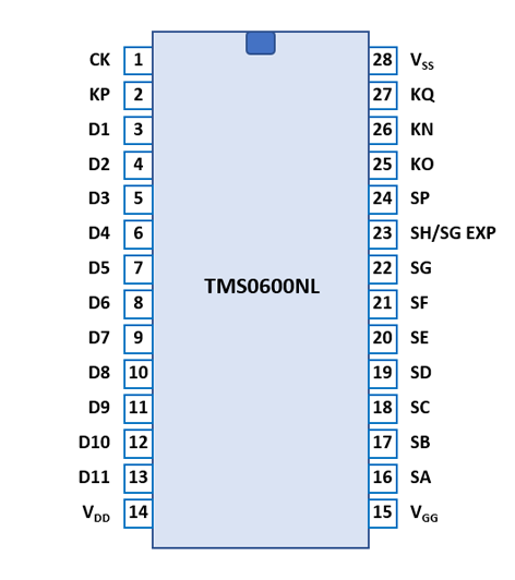
The TMS0600 uses a standard 0.6” wide 28-pin DIP (Dual In-line Package with a 0.1” / 2.54 mm lead pitch).
| Pin | IO | Function | Pin | IO | Function |
| 1 | I | Clock Input | 28 | V | Common Voltage |
| 2 | I | Keymatrix input P | 27 | I | Keymatrix input Q |
| 3 | O | Digit driver 1 (EXP LSD) | 26 | I | Keymatrix input N |
| 4 | O | Digit driver 2 (EXP MSD) | 25 | I | Keymatrix input O |
| 5 | O | Digit driver 3 (LSD) | 24 | O | Segment driver DP |
| 6 | O | Digit driver 4 | 23 | O | Segment driver H/G (EXP) |
| 7 | O | Digit driver 5 | 22 | O | Segment driver G |
| 8 | O | Digit driver 6 | 21 | O | Segment driver F |
| 9 | O | Digit driver 7 | 20 | O | Segment driver E |
| 10 | O | Digit driver 8 | 19 | O | Segment driver D |
| 11 | O | Digit driver 9 | 18 | O | Segment driver C |
| 12 | O | Digit driver 10 (MSD) | 17 | O | Segment driver B |
| 13 | O | Digit driver 11 (OVER) | 16 | O | Segment driver A |
| 14 | V | Negative Voltage VDD | 15 | V | Negative Voltage VGG |
| The Segment drivers A-G and DP (Decimal Point) are connected to the display in the pictured way. | 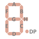 |
| The Segment drivers A-G/H and DP (Decimal Point) are connected to the display in the pictured way. The TMS0602 repurposes the Segment H for the minus sign of the Exponent in the pictured way. | 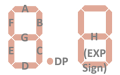 |
The keyboards of all calculators based on the TMS0600 Product Family consist of a x/y-matrix connected to the digit driver outputs D1-D11 and the keymatrix inputs KN (Numbers), KO (Operations), KP (Extended Functions), and KQ (Extended Memory Operations). In the fixed-point output format mode the position of the decimal point is selected with the KP (Decimal Point) input. The Constant/Chain switch is connected between D10-KQ (Constant).
Scanning is performed in D11 → D1 direction at a rate of about 584 Hz:
|
• State Time = 3 Clocks =
0.012 ms @ CK=250 kHz • Digit Time = 13 States (1 Instruction Cycle) = 0.156 ms @ CK=250 kHz • Scan Time = 11 Digit Times (D1 to D11) = 1.712 ms @ CK=250 kHz |
TMS0601 |
TMS0602 |
||||||||
| KN | KO | KP | KQ | KN | KO | KP | KQ | ||
| D1 | 1 | + | [F 1] | D1 | 9 | − | |||
| D2 | 2 | × | [F 2] | D2 | 8 | + | |||
| D3 | 3 | ÷ | [F 3] | D3 | 7 | × | |||
| D4 | 4 | − | [F 4] | M− | D4 | 6 | ÷ | ||
| D5 | 5 | % | [F 5] | D5 | 5 | CD | |||
| D6 | 6 | M+ | [F 6] | D6 | 4 | EE | √x | ||
| D7 | 7 | = | [F 7] | D7 | 3 | +/− | |||
| D8 | 8 | CE | MR | D8 | 2 | = | 1/x | ||
| D9 | 9 | . | D9 | 1 | . | ||||
| D10 | 0 | C | [F 0] | CM | D10 | 0 | PI | x2 | [ - K] |
| D11 | D11 | C | |||||||
TMS0603 |
TMS0604 |
||||||||
| KN | KO | KP | KQ | KN | KO | KP | KQ | ||
| D1 | 1 | + | D1 | 1 | S | ||||
| D2 | 2 | × | D2 | 2 | × | ||||
| D3 | 3 | ÷ | D3 | 3 | ÷ | [ - ∑] | |||
| D4 | 4 | − | D4 | 4 | += | ||||
| D5 | 5 | M+ | X<>Y | D5 | 5 | −= | |||
| D6 | 6 | M− | CM | D6 | 6 | M+= | T | ||
| D7 | 7 | RM | x2 | D7 | 7 | M−= | |||
| D8 | 8 | = | C/CE | D8 | 8 | % | CM | ||
| D9 | 9 | . | 1/x | D9 | 9 | . | |||
| D10 | 0 | X<>M | D10 | 0 | C/CE | [ - K] | |||
| D11 | CA | [ - ∑] | % | D11 | CA | ||||
TMC0605 |
TMC0611 |
||||||||
| KN | KO | KP | KQ | KN | KO | KP | KQ | ||
| D1 | 1 | + | D1 | 1 | + | ||||
| D2 | 2 | × | D2 | 2 | × | ||||
| D3 | 3 | ÷ | D3 | 3 | ÷ | ||||
| D4 | 4 | − | [ - AM] | D4 | 4 | − | |||
| D5 | 5 | = | D5 | 5 | M+ | ||||
| D6 | 6 | √x | D6 | 6 | M− | ||||
| D7 | 7 | T | D7 | 7 | √x | ||||
| D8 | 8 | %± | D8 | 8 | = | %± | |||
| D9 | 9 | . | C | D9 | 9 | . | |||
| D10 | 0 | CE | D10 | 0 | CE | T | |||
| D11 | D11 | C | |||||||
Calculators based on the TMS0600 make use of either 9-digit or 12-digit LED (Light-Emitting-Diode) Displays with common cathode architecture.
If you have additions to the above datasheet please email: joerg@datamath.org.
© Joerg Woerner, December 18, 2021. No reprints
without written permission.