DATAMATH CALCULATOR MUSEUM
|
DATAMATH CALCULATOR MUSEUM |
When Texas Instruments introduced in Fall 1973 the TMS0800 Product Family, its focus was clearly not on desktop calculators. Many features known from the TMS0100 Product Family, like support of 10-digit displays, fix-point selector switch, selectable roundoff and Adding Machine Logic were removed from the specification sheet. Instead the TMS0800 addressed both manufacturing costs and user experience of battery operated handheld calculators, integrating the previously external clock generator and segment drivers, adding a low-battery display and extending the battery life with an optional timeout feature. The algorithm of the chips were improved, too; the TMS0803 for example features an Automatic Constant for all four functions, integrates a percent function and even allows for Decimal Alignment for addition and subtraction.
Texas Instruments introduced in Summer 1974 with the TMS0850 Product Family a variation of the TMS0800 with redesigned segment and digit output drivers, directly interfacing with low-voltage Vacuum Fluorescent Displays (VFDs) up to 35 Volts. The last step in the evolution of the TMS0800 could be found with the TMS0830 Product Family introduced in Winter 1974, technically identical with the TMS0800 but specified for 9 Volts battery operation.
We assume that less than ten designs were realized with the TMS0850 Product Family. As of today we know with the TMS0851 and TMS0855 two catalog products and with the TMS0852 a Texas Instruments' internal version developed for the failed TI-150 calculator.
A typical calculator built around the TMS0850 series performs the four basic functions +, −, ×, and ÷ and might add the %- or √x-functions.
Manufacturers of battery operated 5-function handheld calculators could select in 1975 between more than a dozen American, European and Japanese calculator chip suppliers, namely AMI, Cal-Tex, Commodore/MOS Technology, Electronic Arrays, General Instrument, Hitachi, Litronix, Matsushita, Mitsubishi, Mostek, National Semiconductor, NEC, Omron, RFT, Rockwell, Sharp, Texas Instruments, Toshiba, and Western Digital. While Texas Instruments owned in 1972/1973 the market of single-chip calculator circuits with the famous TMS0100 series, offered in 1975 many of these companies more functionality than the TMS0800 design could offer with its limited Instruction ROM with only 320 Words * 11 Bits capacity. Texas Instruments consequently replaced the TMS0800 early in 1975 with the TMS0950 and the TMS0850 in 1976 with the TMS1040, both offering an enlarged Instruction ROM of 1,024 Words * 8 Bits capacity.
| Type | Calculators | Keyboard | Constant (M-D-A-S) |
Digits | Fixed DP | Timeout | Rounding | Special Functions |
Seg./Dig. Blanking |
(6,7,9) Font |
Seg. H Low V. |
Entry Overflow |
Calculating Overflow |
| TMS0851 | Privileg 804 D, Sovrin Model 128, | [+][−][=] | 1-2-2-2 | 8 | Float (A-S) Auto |
Yes | None | [%] | NONE S1, S11 |
||||
| TMS0852 | TI-150 | [+][−][=] | 1-2-2-2 | 8 | Float (A-S) Auto |
No | None | [%] | S1, S11 S1, S11 |
||||
| TMS0855 | Canon Panther D, LD-80, Homeland 8011 | [+][−][=] | 1-2-2-2 | 8 | Float | Yes | None | [%±][√x][RE] | NONE S1, S11 |
|
| Description | Comments | |
| Architecture | Single-chip Calculator | Second Generation |
| Category | Register Processor | BCD-serial |
| Related |
TMS0800 TMS0830 |
16 Volts Operation, LED 9 Volts Operation, LED |
| ROM Size | 3,520 Bits | 320 Words * 11 Bits |
| RAM Size | 154 Bits | 3 Registers * 11 Digits, 2 * 11 Bit-Flags |
| Outputs | 9 Digits 8/9 Segments |
VFD Digit Drivers VFD Segment Drivers |
| Inputs | 3 Keyboard 0/1 Low Voltage Detection |
Digit to Keyboard Scan-Matrix |
Capacity: Up to 8 digits (positive and negative)
Logic: Algebraic Chain Logic with Automatic Constant
[2] [x] [3] [+] [4] [x] [5] [=] → '50.'
Number Entry: Right-justified number entry, entering a ninth digit is ignored
[1] [2] [3] [4] [5] [6] [7] [8] [9] → '12345678.'
Decimal Point: First entered decimal point is used, additional decimal point entries are ignored
[1] [.] [2] [.] [3] → '1.23'
Fixed Decimal Point: Fixed decimal point arithmetic is not supported
Decimal Alignment: Decimal alignment is supported for additions and subtractions
[0] [.] [4] [5] [+] [0] [.] [5] [5] [=] → '1.00'
Clear: Automatic power-up clear implemented. [C] key clears the whole calculator, [CE] key clears last entry of a number
[1] [+] [2] [C] [3] [=] → '3.'; [1] [+] [2] [CE] [3] [=] → '4.'
Change Sign: Not supported. When performing multiplication or division, a negative value is assigned to a number by pressing the [−] key before entering the number
[−] [2] [x] [3] [=] → '-6.'; [−] [2] [x] [−] [3] [=] → '6.'
Number Display: Right-justified number display with leading-zero suppression
Negative Numbers: Negative numbers are shown with '-' floating immediate left of the number
Calculating Overflow: An overflow shows the result with the decimal point shifted 8 positions to the left and 'C' (or 'E' for negative numbers) in the leftmost position. It is recoverable using the [C] or [CE] keys
[1] [2] [3] [4] [5] [x] [1] [2] [3] [4] [5] [=] → 'C1.5239902'
Divide By Zero: A division of a positive or negative number by zero shows a '0' and 'C' in the leftmost position. It is recoverable using the [C] or [CE] keys
[1] [:] [0] [=] → 'C 0.'; [−] [1] [:] [0] [=] → 'C 0.'
Timeout: If selected, the display blanks out about 20 seconds after the last operation and shows only a '-' in the leftmost digit. Timeout is recoverable with an optional [D] key or interrupted with the [=], [C] or [CE] keys
[1] [2] .. 20 seconds → '-', [D] [3] → '123.'
Rounding: Rounding of displayed calculating results is not supported
[2] [0] [:] [3] [=] → '6.6666666'
Automatic Constant: Implemented for multiplication (1st number used as constant), division (2nd), addition (2nd), and subtraction (2nd)
[3] [x] [2] [=] [=] → '18.', [1] [=] → '3.'; [4] [x] [=] [=] → '64.'
[3] [:] [2] [=] [=] → '0.75', [1] [=] → '0.5.'; [4] [:] [=] [=] → '0.25'
[3] [+] [2] [=] [=] → '7.', [1] [=] → '3.'; [4] [+] [=] [=] → '12.'
[3] [−] [2] [=] [=] → '-1.', [1] [=] → '-1.'; [4] [−] [=] [=] → '-4.'
Percent Function: The [%] key is implemented for addition, subtraction, multiplication, and division. Using the [=] key following the [%] key in multiplication or division leads to unexpected result
[2] [0] [+] [5] [%] → '1.', [=] → '21.'
[2] [0] [−] [5] [%] → '-1.', [=] → '19.'
[2] [0] [x] [5] [%] → '1.', [=] → '21.'
[5] [:] [2] [0] [%] → '25.', [=] → '1.25'
Known Calculator Logic Bugs:
Residual Trailing Zero Bug: Certain calculations result in displaying trailing zeros
[1] [:] [1] [0] [0] [0] [0] [=] → '0.0001', [=] → '0.', [+] [1] [=] → '1.0000'
Capacity: Up to 8 digits (positive and negative)
Logic: Algebraic Chain Logic with Automatic Constant
[2] [x] [3] [+] [4] [x] [5] [=] → '50.'
Number Entry: Right-justified number entry, entering a ninth digit is ignored
[1] [2] [3] [4] [5] [6] [7] [8] [9] → '12345678.'
Decimal Point: First entered decimal point is used, additional decimal point entries are ignored
[1] [.] [2] [.] [3] → '1.23'
Fixed Decimal Point: Fixed decimal point arithmetic is not supported
Decimal Alignment: Decimal alignment is supported for additions and subtractions
[0] [.] [4] [5] [+] [0] [.] [5] [5] [=] → '1.00'
Clear: Automatic power-up clear implemented. [C] key clears the whole calculator, [CE] key clears last entry of a number
[1] [+] [2] [C] [3] [=] → '3.'; [1] [+] [2] [CE] [3] [=] → '4.'
Change Sign: Not supported. When performing multiplication or division, a negative value is assigned to a number by pressing the [−] key before entering the number
[−] [2] [x] [3] [=] → '-6.'; [−] [2] [x] [−] [3] [=] → '6.'
Number Display: Right-justified number display with leading-zero suppression
Negative Numbers: Negative numbers are shown with '-' floating immediate left of the number
Calculating Overflow: An overflow shows the result with the decimal point shifted 8 positions to the left and 'C' (or 'E' for negative numbers) in the leftmost position. It is recoverable using the [C] or [CE] keys
[1] [2] [3] [4] [5] [x] [1] [2] [3] [4] [5] [=] → 'C1.5239902'
Divide By Zero: A division of a positive or negative number by zero shows a '0' and 'C' in the leftmost position. It is recoverable using the [C] or [CE] keys
[1] [:] [0] [=] → 'C 0.'; [−] [1] [:] [0] [=] → 'C 0.'
Timeout: Not supported
Rounding: Rounding of displayed calculating results is not supported
[2] [0] [:] [3] [=] → '6.6666666'
Automatic Constant: Implemented for multiplication (1st number used as constant), division (2nd), addition (2nd), and subtraction (2nd)
[3] [x] [2] [=] [=] → '18.', [1] [=] → '3.'; [4] [x] [=] [=] → '64.'
[3] [:] [2] [=] [=] → '0.75', [1] [=] → '0.5.'; [4] [:] [=] [=] → '0.25'
[3] [+] [2] [=] [=] → '7.', [1] [=] → '3.'; [4] [+] [=] [=] → '12.'
[3] [−] [2] [=] [=] → '-1.', [1] [=] → '-1.'; [4] [−] [=] [=] → '-4.'
Percent Function: The [%] key is implemented for addition, subtraction, multiplication, and division. Using the [=] key following the [%] key in multiplication or division leads to unexpected result
[2] [0] [+] [5] [%] → '1.', [=] → '21.'
[2] [0] [−] [5] [%] → '-1.', [=] → '19.'
[2] [0] [x] [5] [%] → '1.', [=] → '21.'
[5] [:] [2] [0] [%] → '25.', [=] → '1.25'
Known Calculator Logic Bugs: NoneCapacity: Up to 8 digits (positive and negative)
Logic: Algebraic Chain Logic with Automatic Constant
[2] [x] [3] [+] [4] [x] [5] [=] → '50.'
Number Entry: Right-justified number entry, entering a ninth digit is ignored
[1] [2] [3] [4] [5] [6] [7] [8] [9] → '12345678.'
Decimal Point: First entered decimal point is used, additional decimal point entries are ignored
[1] [.] [2] [.] [3] → '1.23'
Fixed Decimal Point: Fixed decimal point arithmetic is not supported
Decimal Alignment: Decimal alignment is not supported
[0] [.] [4] [5] [+] [0] [.] [5] [5] [=] → '1.'
Clear: Automatic power-up clear implemented. [C] key clears the whole calculator, [CE] key clears last entry of a number
[1] [+] [2] [C] [3] [=] → '3.'; [1] [+] [2] [CE] [3] [=] → '4.'
Change Sign: Not supported. When performing multiplication or division, a negative value is assigned to a number by pressing the [−] key before entering the number
[−] [2] [x] [3] [=] → '-6.'; [−] [2] [x] [−] [3] [=] → '6.'
Number Display: Right-justified number display with leading-zero suppression
Negative Numbers: Negative numbers are shown with '-' in the left most position
Calculating Overflow: An overflow shows the result with the decimal point shifted 8 positions to the left and 'u' (or 'o for negative numbers) in the leftmost position. It is recoverable using the [C] or [CE] keys
[1] [2] [3] [4] [5] [x] [1] [2] [3] [4] [5] [=] → 'u1.5239902'
Divide By Zero: A division of a positive or negative number by zero shows a '0' and 'u' or 'o' respectively in the leftmost position. It is recoverable using the [C] or [CE] keys
[1] [:] [0] [=] → 'u 0.'; [−] [1] [:] [0] [=] → 'o 0.'
Timeout: If selected, the display blanks out about 20 seconds after the last operation and shows only a '-' in the leftmost digit. Timeout is recoverable with an optional [D] key or interrupted with the [=], [C] or [CE] keys
[1] [2] .. 20 seconds → '-', [D] [3] → '123.'
Rounding: Rounding of displayed calculating results is not supported
[2] [0] [:] [3] [=] → '6.6666666'
Automatic Constant: Implemented for multiplication (1st number used as constant), division (2nd), addition (2nd), and subtraction (2nd)
[3] [x] [2] [=] [=] → '18.', [1] [=] → '3.'; [4] [x] [=] [=] → '64.'
[3] [:] [2] [=] [=] → '0.75', [1] [=] → '0.5.'; [4] [:] [=] [=] → '0.25'
[3] [+] [2] [=] [=] → '7.', [1] [=] → '3.'; [4] [+] [=] [=] → '12.'
[3] [−] [2] [=] [=] → '-1.', [1] [=] → '-1.'; [4] [−] [=] [=] → '-4.'
Percent Function: The [%±] is implemented for addition and subtraction for add-on and discount calculations
[2] [0] [x] [5] [%±] → '1.', [+] [=] → '21.'
[2] [0] [x] [5] [%±] → '1.', [−] [=] → '19.'
Register Exchange: The [RE] key allows the exchange of the display register with the operand register before completing the calculation
[2] [:] [3] → '3.', [RE] → '1,5.', [=] → '0.75.'
Known Calculator Logic Bugs:
Negative Square Root Bug: Negative square roots are allowed and result in a negative number
[8] [√x] → '2.8284271'; [−] [8] [√x] → '-2.8284271'
Zero Square Root Bug: Calculating the square root immediately after a previous calculation that resulted in a zero is generating an erroneous display
[1] [−] [1] [=] → '0.', [√x] → '0.0000000'
Square Root Chain Bug: The result of a square root calculation can't be used as an operand in a chain calculation w/o pressing the [=] key before the function key
[4] [√x] → '2.', [+] [1] [=] → '1.'
[4] [√x] → '2.', [=] → '2.', [+] [1] [=] → '3
| Device | Top Markings Bottom Markings |
Calculator Serial Number |
Instruction ROM ©Texas Instruments |
| TMS0851NL | TMS0851NL P7515 J0851P |
Sovrin Model 128 505274 |
|
| TMS0852NC | TMS0852NC 7445-1 B0852 |
TI-150 494 016294 |
|
| TMS0855NC | TMS0855NC A7435 J0855A 34 |
Canon LD-80 500476 |
IMPORTANT NOTE: This information is provided as a service of the Datamath Calculator Museum to enthusiasts of early Texas Instruments calculators and please be aware that the Copyright of the Software transcribed in the ROM Images, the underlying algorithm or application might be owned by Texas Instruments or other third parties. The commercial use of the published Recorded ROM Images is strictly prohibited. In case of questions please contact us using the email address listed in the footer of this webpage.
| Item | Min | Typ | Max | Unit | Comments |
| VSS | 0 | V | |||
| VDD | -16.3 | -10.0 | -9.5 | V | |
| VGG | -16.3 | -15.8 | -15.3 | V | |
| VOUT | -35 | -30 | 0.3 | V | VFD Output Voltage through 100 kOhm Resistors |
| VIN (KN-KP) | -35 | -30 | 0.3 | V | Input Voltage through 100 kOhm Resistors |
| IDD (VDD = -10.0 V) | 1.8 | mA | REXT = 100 kOhm, Segment- and | ||
| IDD (VDD = -15.8 V) | 2.2 | mA | Digit-Driver Load 100 kOhm to VDD | ||
| IGG | 1.6 | mA | |||
| Int. CK | 100 | 160 | 200 | kHz | REXT = 100 kOhm to VDD |
| Ext. CK | 100 | 160 | 200 | kHz | REXT = 0 Ohm to VSS |
CLOCK GENERATOR
All devices of the TMS0850 Product Family include an internal clock oscillator that can be enabled by pulling Pin 14 (REXT/Clock Select) with a resistor REXT to VDD. The internal clock frequency is then output on Pin 13 (OSC Out/Clock Input) for test purposes. Connecting Pin 14 directly to VSS disables the internal clock oscillator and the chip can be operated through an external clock signal with frequencies between 100 kHz and 200 kHz applied to Pin 13. The external clock frequency should have a duty cycle close to 50% and oscillate between VSS and VDD.
The frequency of the internal clock oscillator is set with the external resistor REXT, its nominal value is 100 kOhm for a typical frequency of 160 kHz. We observed values between 100 kOhm and 180 kOhm used on the printed circuit boards (PCBs) of various calculator based on TMS0850 devices. Here at the Datamath Calculator Museum we operate the TMS0850 Devices-under-Test (DUT) with an external 100 kOhm resistor but verify its operation between 50 kOhm and 150 kOhm.
The operating frequency of the internal clock oscillator depends not only on the external resistor, but its supply voltages VDD and VGG, too. We observed with our DUT opposite gradients of the oscillation frequency for VDD and VGG variations.
LOW VOLTAGE DETECTION
The chip design of the TMS0850 single-chip calculator circuit allows to configure Pin 5 (SH/LV) either as Segment Driver Output H (used for the Fancy Four) or as Low Voltage Input to display a warning symbol like 'L' on the leftmost position of a 9-digit LED (Light-Emitting-Diode) Display. All known designs of the TMS0850 use Pin 5 configured as Low Voltage Input but only few designs make actually use of it. Having Pin 5 floating open or tied to VSS will disable outputting the warning symbol on Digit D9, pulling it down to VDD enables the warning output. We observed with our DUT a threshold of about -2.8 V and measured the internal pull-up resistor with about 25k Ohm at VLV = -2.0 V.
TIMEOUT FEATURE
To increase the operating time of battery-powered handheld calculators, Texas Instruments designed for the TMS0850 Product Family a so-called Timeout feature. When no key presses are detected for about 20 seconds, the display blanks out and shows only a '-' in the leftmost digit to reduce power consumption of the calculator. Timeout is recoverable with an optional [D] key connected between the WDK Output and either the KN or KO Inputs, or pressing any key assigned to the keyboard scan matrix D8, D9/KN, KO, KP.
All designs of the TMS0850 Product Family have the [C] and [=] keys assigned to the D8 and/or D9 keyboard scan outputs, allowing to recover Timeout with these two keys. Many calculators do not make use of the Timeout feature and simply connect Pin 10 (WDK) and Pin 8 (KN) with a short trace on the printed circuit board (PCB).
The Datamath Calculator Museum DCM-50A (Platform) supports the TMS0850 Product Family with its center TMS0800 Textool Test Socket set to DCM-50A (TMS0800) mode. Both Characterization of TMS0850 Calculator Circuits and Reverse-engineering of TMS0850 Calculator Circuits is supported by the DCM-50A (TMS0800).
The DCM-50A Sidekick TMS0800 ROM Recorder attached to the DCM-50A (TMS0800) allows Recording of all TMS0800 Product Family Members including the TMS0830 and TMS0850 Devices.
The TMS0850 was manufactured in a 6 um metal gate PMOS process (metal width = 0.25 mil / 6.0 um, metal spacing = 0.30 mil / 8.0 um, diffusion width = 0.25 mil / 6.0 um, diffusion spacing = 0.25 mil / 6.0 um).
The die size of the TMS0850 is approximately 160 mils * 155 mils / 4.1 mm * 4.0 mm.
The TMS0850 uses a standard 0.6” wide 28-pin DIP (Dual In-line Package with a 0.1” / 2.54 mm lead pitch).
| Pin | IO | Function | Pin | IO | Function |
| 1 | O | Segment driver D | 28 | O | Segment driver C |
| 2 | O | Segment driver E | 27 | O | Segment driver B |
| 3 | O | Segment driver F | 26 | O | Segment driver A |
| 4 | O | Segment driver G | 25 | O | Segment driver DP |
| 5 | IO | Seg. H/Low Voltage | 24 | O | Digit driver 9 (sign) |
| 6 | I | Key-matrix input P | 23 | O | Digit driver 8 (MSD) |
| 7 | I | Key-matrix input O | 22 | O | Digit driver 7 |
| 8 | I | Key-matrix input N | 21 | O | Digit driver 6 |
| 9 | I | Test (VSS) | 20 | O | Digit driver 5 |
| 10 | O | Digit scan DK | 19 | O | Digit driver 4 |
| 11 | V | Negative Voltage VDD | 18 | O | Digit driver 3 |
| 12 | V | Negative Voltage VGG | 17 | O | Digit driver 2 |
| 13 | IO | OSC Out/Clock Input | 16 | O | Digit driver 1 (LSD) |
| 14 | I | REXT/Clock Select | 15 | V | Common Voltage VSS |
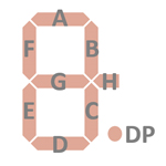
| The Segment drivers A-G and DP (Decimal Point) are
connected to the display in the pictured way. The optional SH/LV signal can be configured as Segment H or Low Voltage indicator. |
 |
The keyboards of all calculators based on the TMS0850 Product Family consist of an x/y-matrix connected to nine digit-driver outputs and the key-matrix inputs KN (Numbers), KO (Operations) and KP (Additional Operations).
The TMS0800 integrates a timer to shut off the display after a certain amount of time with the calculator not in use, the reset of the timer can be accomplished either with an extra [D] key connected between the digit scan DK signal and the key-matrix input KO line or simply by shorting DK output with the KN input.
Scanning is performed in D9 → D1 direction at a rate of about 370 Hz:
|
• State Time = 4 Clocks = 0.025 ms @ CK=160 kHz • Digit Time = 11 States (1 Instruction Cycle) = 0.275 ms @ CK=160 kHz • Scan Time = 10 Digit Times (D1 to D10 with D10 a dead cycle) = 2.75 ms @ CK=160 kHz |
TMS0851 |
TMS0852 |
||||||
| KN | KO | KP | KN | KO | KP | ||
| D1 | 9 | 0 | D1 | 9 | 0 | ||
| D2 | 8 | . | D2 | 8 | . | ||
| D3 | 7 | % | D3 | 7 | % | ||
| D4 | 6 | ÷ | D4 | 6 | ÷ | ||
| D5 | 5 | × | D5 | 5 | × | ||
| D6 | 4 | − | D6 | 4 | − | ||
| D7 | 3 | + | D7 | 3 | + | ||
| D8 | 2 | = | CE | D8 | 2 | = | CE |
| D9 | 1 | C | D9 | 1 | C | ||
| DK | -TR- | (D) | DK | ||||
TMS0855 |
|||
| KN | KO | KP | |
| D1 | 9 | 0 | |
| D2 | 8 | . | |
| D3 | 7 | ÷ | |
| D4 | 6 | × | |
| D5 | 5 | − | |
| D6 | 4 | + | |
| D7 | 3 | = | %± |
| D8 | 2 | CE | √x |
| D9 | 1 | C | RE |
| DK | -TR- | (D) | |
Calculators based on the TMS0850 make use of 9-digit low-voltage VFDs (Vacuum Fluorescent Displays).
If you have additions to the above datasheet please email: joerg@datamath.org.
© Joerg Woerner, August 18, 2024. No reprints
without written permission.


