DATAMATH CALCULATOR MUSEUM
|
DATAMATH CALCULATOR MUSEUM |
Texas Instruments introduced in Summer 1974 with the TMS3834 their first Digital Alarm Clock Chip to compete with the wildly popular National Semiconductor MM5314N Clock Chip and both Mostek's MK50250N and CalTex's CT7001 Alarm Clock Chips. While most available Chips supported a 6-digit readout, focused Texas Instruments on the growing market of Alarm Clock Radios with just a 4-digit readout.
The TMS3834 was developed by a Texas Instruments design team in France used to 24-hour clocks, a convention of timekeeping in which the day runs from midnight to midnight and is divided into 24 hours. This is indicated by the hours passed since midnight, from 0 to 23. The daily cycle starts at 00:00, runs through 12:00 noon, and continues until 23:59 just before midnight at the end of the day.
The 12-hour clock used mainly in North America and a few other regions of the World, is a time convention in which the 24 hours of the day are divided into two periods: a.m. (from Latin ante meridiem, translating to "before midday") and p.m. (from Latin post meridiem, translating to "after midday"). Each period consists of 12 hours numbered: 12 (acting as 0), 1, 2, 3, 4, 5, 6, 7, 8, 9, 10 and 11. The daily cycle starts at 12 midnight (usually indicated as 12:00 a.m.), runs through 12 noon (usually indicated as 12:00 p.m.), and continues until just before midnight at the end of the day.
With the implementation of the 12-hour clock as an afterthought by TI's engineering team and not considering the role of 12 acting as 0, an interesting "p.m.bug" was introduced into the TMS3834 making its sales in North America almost impossible. Twice a day the p.m. indicator is off by up to one hour:
| 24-hour clock | 12-hour clock | TMS3834 12-hour clock |
| 00:00 | 12:00 a.m. | 12:00 (PM) |
| 00:59 | 12:59 a.m. | 12:59 (PM) |
| 01:00 | 1.00 a.m. | 1:00 |
| 11:59 | 11:59 a.m. | 11:59 |
| 12:00 | 12:00 p.m. | 12:00 |
| 12:59 | 12:59 p.m. | 12:59 |
| 13:00 | 1:00 p.m. | 1:00 (PM) |
| 23:59 | 11:59 p.m. | 11:59 (PM) |
Texas Instruments' TI-70 Digital Clock and TI-71 Digital Alarm Clock are consequently the only known products sold in the US and Canada and using the TMS3834, while in Europe a plethora of Alarm Clocks and Alarm Clock Radios sporting both LED Displays and Vacuum Fluorescent Displays were based on this chip.
Please don't miss page 4 of the TI-71 Manual explaining the "p.m. bug":
|
• For setting time from 1:00 p.m. to 12:59 a.m., PM GLOWING DOT should be ON. • For setting time from 1:00 a.m. to 12:59 p.m., PM GLOWING DOT should be OFF. |
The feature set of the TMS3834 includes:
|
• 4-digit display, 7-segment output • 50 Hz or 60 Hz operation • 12-hour or 24-hour display format • PM indicator (It is not a bug, it is a feature) • Leading-zero blanking (12-hour format) • 24-hour Alarm with Snooze • Output Enable Control • Direct drive of low-voltage VF-Displays • Single power supply |
The block diagram of the TMS3834 Digital Alarm Clock Chip is centered around a Time Counter for the present time, an Alarm Counter for the alarm time, a multiplexer for the two 4-digit counter outputs with a 1:4 Decoder to multiplex the four digits and a BCD-7-segment decoder with output inverters. An integrated 100 kHz Oscillator with a divide-by-64 counter is providing the 400 Hz scan clock for the display and some internal housekeeping tasks. A Shaper circuitry accepts a low-voltage 50 Hz or 60 Hz AC-signal and feeds a selectable divide-by-50/60 counter to create the 1-second time clock used to set the time and alarm and flashing the colon (PM Output) in 24-hour display format. A second Shaper/Memory circuitry feeds the various control inputs to the Gating Logic which selects Time Counter or Alarm Counter, monitors the Alarm Comparator and activates both the PM Signal (in 12-hour mode) and ALARM Output.
All Control Signals have internal pull-down resistors, allowing the connection of push-buttons or sliding switches between VSS and the respective input to activate them or simply keep them unconnected:
|
• 50/60 SELECT: VSS - 50 Hz operation, n.c. or VDD – 60 Hz operation • 12/24 SELECT: VSS – 12-hour operation, n.c. or VDD 24-hour operation • CHIP ENABLE: VSS – Display off, n.c. or VDD – Display on • FAST: VSS pulse – increment Hour Counter by one, VSS – increment Hour Counter by one every second • SLOW: VSS pulse – increment Minute Counter by one, VSS – increment Minute Counter by one every second • SECONDS: VSS – Display Hours and Minutes, n.c. or VDD – Display Minutes and Seconds • HOLD: VSS – hold Second Counter to synchronize Minute Counter with reference time while setting time • SET ALARM: VSS – Set Alarm with FAST and SLOW Inputs, n.c. or VDD – Set Time • ON/OFF ALARM: VSS – Alarm activated, n.c. or VDD – Alarm off • SNOOZE: VSS pulse – Stop Alarm for 6-7 minutes |
| Type | Product | Digits | Functions |
| TMS3834 | TI-70 | HH:MM. | Clock |
| TMS3834 | TI-71 | .HH:MM. | Alarm Clock |
| Revision | Products | First Prototypes | Comments Known Date Codes |
| TMS3834A | TI-70, TI-71 | June 1974 | 7423: A70-1003921, 364 7424: A70-1013272, 314 |
| TMS3834 (D) | TI-70, TI-71 | Bottom Marking D 3834 7431: A70-1003668, 364 7433: A70-1010745, 484 7441: A71-1030218, 135 7441: A71-1030794, 145 |
|
| TMS3834B | TI-70, TI-71 | 7605: A71-1025183, 085 |
| Item | Min | Typ | Max | Unit | Comments |
| VSS | 0 | V | |||
| VDD | -19.0 | -14.0 | -11.0 | V | |
| Output Voltage with VDD applied | -35.0 | V | Direct interface to low-voltage VF-Displays |
||
| CK | 100 | kHz | Internal oscillator |
The TMS3834 was manufactured in a metal gate PMOS process.
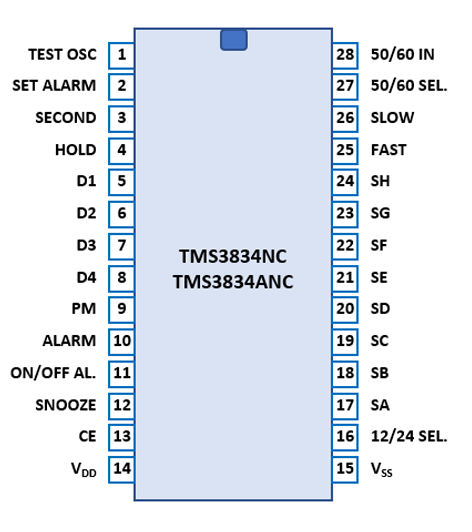
The TMS3834 and TMS3834A use a 0.6” wide 28-pin DIP (Dual In-line Package with a 0.1” / 2.54 mm lead pitch).
| Pin | IO | Function | Pin | IO | Function |
| 1 | O | Test Oscillator | 28 | I | 50/60 Hz Input |
| 2 | I | Set Alarm | 27 | I | 50/60 Hz Select |
| 3 | I | Display MM:SS | 26 | I | Slow (Minute) |
| 4 | I | Hold Seconds | 25 | I | Fast (Hour) |
| 5 | O | Digit driver 1 (leftmost) | 24 | O | Segment driver H |
| 6 | O | Digit driver 2 | 23 | O | Segment driver G |
| 7 | O | Digit driver 3 | 22 | O | Segment driver F |
| 8 | O | Digit driver 4 (rightmost) | 21 | O | Segment driver E |
| 9 | O | PM or Flashing Colon | 20 | O | Segment driver D |
| 10 | O | Alarm Output | 19 | O | Segment driver C |
| 11 | I | Alarm On/Off | 18 | O | Segment driver B |
| 12 | I | Snooze | 17 | O | Segment driver A |
| 13 | I | Chip Enable | 16 | I | 12/24 Select |
| 14 | V | Positive Voltage VDD | 15 | V | Positive Voltage VSS |
| The Segment drivers A-G, Alarm Indicator, Upper Colon Indicator, Lower Colon Indicator, PM Indicator and Digit drivers are connected to the display in the pictured way. | 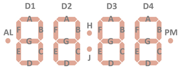 |
The keys and switches to control the functions of the TMS3834 are connected directly to discrete Input-Pins of the TMS3834.
Clocks, Alarm Clocks, and Alarm Clock Radios based on the based on the TMS3834 make use of either a 4-digit VFD (Vacuum-Fluorescent-Display) or a 4-digit LED (Light-Emitting-Diode) Display like the TIL370 found with the TI-70 and TI-71.
If you have additions to the above datasheet please email: joerg@datamath.org.
© Joerg Woerner, October 15, 2021. No reprints
without written permission.