DATAMATH CALCULATOR MUSEUM
|
DATAMATH CALCULATOR MUSEUM |
These Four-Digit Clock/Timer Numeric Seven-Segment LED Displays are intended for use under pulsed conditions by enabling the common cathode of each digit sequentially and enabling the desired Segment anode and Alarm Indicator, Upper Colon Indicator, and Lower Colon Indicator anodes in phase with the character enabling pulse. The pulse rate is kept high enough so that light from each character appears to the eye to be constant. The PM Indicator is accessible with separate anode and cathode terminals for constant on/off operation.
|
• 0.5”/12.7 mm Characters • Seven-Segment Digits • Continuous Uniform Segments • Wide Viewing Angle • Common-Cathode Configuration for Multiplex Applications • 0.6”/15.1 mm and 0.8”/21.1 mm |
The TIL370 is a member of a whole portfolio of similar products with different LED colors and different populated LED segments:
| 12-Hour Displays | 24-Hour Displays | |||
| RED | TIL364 | TIL367 | TIL370 | TIL373 |
| GREEN | TIL365 | TIL368 | TIL371 | TIL374 |
| AMBER | TIL366 | TIL369 | TIL372 | TIL375 |
| Segments D1 | B & C | B & C | A - G | A - G |
| Alarm Ind. | Yes | No | Yes | No |
| PM Indicator | Yes | Yes | No | No |
Please notice that the TIL370 used with the TI-70 and TI-71 sports the PM Indicator, too.
| Type | Products | Digits | Comments |
| TIL370 | TI-70, TI-71 | 4 digits |
| Item | Min | Typ | Max | Unit | Comments |
| Display Width |
3.190 81.03 |
3.200 81.28 |
3.210 81.53 |
inch mm |
|
| Display Height |
1.020 25.91 |
1.030 26.16 |
1.040 26.42 |
inch mm |
|
| Display Depth |
0.201 5.11 |
0.211 5.36 |
0.221 5.61 |
inch mm |
Including Printed Circuit Board, without Plastic Extrusion of Lens |
| PCB Thickness |
0.031 0.8 |
inch mm |
|||
| Lens Width |
3.086 78.4 |
inch mm |
|||
| Lens Height |
0.740 18.8 |
inch mm |
|||
| Lens Depth |
0.180 4.6 |
inch mm |
|||
| Character Height |
0.500 12.70 |
inch mm |
|||
| Character Width |
0.310 7.87 |
inch mm |
|||
| Character Slant Angle |
7.5 | degrees | |||
| Indicator Diameter |
0.050 1.27 |
inch mm |
|||
| Character Spacing |
0.600 15.24 |
inch mm |
|||
| Indicator Spacing |
0.400 10.16 |
inch mm |
|||
| Peak Forward Current |
200 | mA | Each Segment or Indicator over maximal 16.66 ms |
||
| Average Forward Current |
25 | mA | Each Segment or Indicator | ||
| Luminous Intensity | 240 600 |
95 240 |
µcd | Each Segment at IF = 20 mA Each Indicator at IF = 20 mA |
|
| Wavelength at Peak Emission |
640 | 655 | 680 | nm | Spectral bandwidth 20 nm |
| Static Forward Voltage | 1.7 | 2 | V | At IF = 10 mA |
The displays are formed by placing a one-piece reflector assembly within a transparent plastic case which is attached to a printed circuit board that contains the individual GaAsP (Gallium Arsenide Phosphide) LED chips.
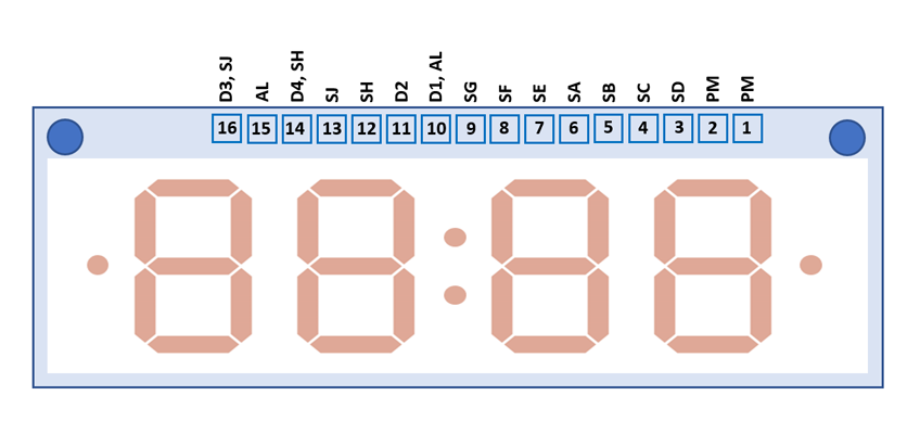
The TIL370 uses a 3.2" / 81.28 mm by 1.03” / 26.13 mm rectangular printed circuit board (PCB) with 16 solder tabs with a 0.125” / 3.18 mm pitch arranged on the bottom of the display module.
| Pin | Pol. | Function |
| 1 | C | PM Indicator |
| 2 | A | PM Indicator |
| 3 | A | D Segments |
| 4 | A | C Segments |
| 5 | A | B Segments |
| 6 | A | A Segments |
| 7 | A | E Segments |
| 8 | A | F Segments |
| 9 | A | G Segments |
| 10 | C | Digit 1, Alarm Indicator |
| 11 | C | Digit 2 |
| 12 | A | H Indicator (Upper Colon) |
| 13 | A | J Indicator (Lower Colon) |
| 14 | C | Digit 4, H Indicator |
| 15 | A | Alarm Indicator |
| 16 | C | Digit 3, J Indicator |
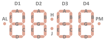
| The Anode of the Segments A-G, Alarm Indicator, Upper Colon Indicator, and Lower Colon Indicator and the Cathode of the Digits 1-4 and the Anode and Cathode of the separate PM Indicator are connected to the display in the pictured way. |
 |
If you have additions to the above datasheet please email: joerg@datamath.org.
© Joerg Woerner, October 16, 2021. No reprints
without written permission.