DATAMATH CALCULATOR MUSEUM
|
DATAMATH CALCULATOR MUSEUM |
Canon Canola L813 II
| Date of introduction: | March 1982 | Display technology: | Fluorescent |
| New price: | Display size: | 8 | |
| Size: | 6.3" x 5.2" x
1.8" 159 x 132 x 45 mm3 |
||
| Weight: | 9.5 ounces, 269 grams | Serial No: | 445503 |
| Batteries: | 4*AA or NiCd Pack-5 | Date of manufacture: | mth 08 year 1984 |
| AC-Adapter: | AD-1 | Origin of manufacture: | Japan |
| Precision: | 8 | Integrated circuits: | TMS1045 (___T8432) |
| Memories: | 1 | Displays: | Futaba 9-BT-18A |
| Program steps: | Courtesy of: | Joerg Woerner |
![]()
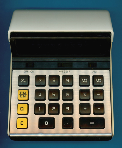
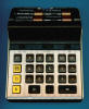
 At
first glance looks this Canon Canola L813 II introduced in 1982 like its
predecessor Canola L813 and even the keyplate states "Canon Canola L813". A
closer examination of the two calculators reveals a slightly different
functionality and keyboard layout, a typical sign of switching from one
single-chip calculator circuit to another one during the life-cycle of the
product. While the original Canola L813 uses a TMS1045 chip...
At
first glance looks this Canon Canola L813 II introduced in 1982 like its
predecessor Canola L813 and even the keyplate states "Canon Canola L813". A
closer examination of the two calculators reveals a slightly different
functionality and keyboard layout, a typical sign of switching from one
single-chip calculator circuit to another one during the life-cycle of the
product. While the original Canola L813 uses a TMS1045 chip...
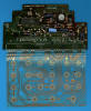
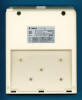
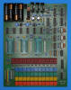
 Dismantling the featured
Canola L813 II calculator manufactured in August 1984 reveals a very cost effective
design using a double-sided printed circuit board
(PCB) centered around a - surprise, surprise - TMS1045 single-chip calculator circuit connected to a 9-digit
Vacuum Fluorescent Display (VFD), a keyboard assembly using a flexible PCB and powered by
4 AA-sized
alkaline batteries.
Dismantling the featured
Canola L813 II calculator manufactured in August 1984 reveals a very cost effective
design using a double-sided printed circuit board
(PCB) centered around a - surprise, surprise - TMS1045 single-chip calculator circuit connected to a 9-digit
Vacuum Fluorescent Display (VFD), a keyboard assembly using a flexible PCB and powered by
4 AA-sized
alkaline batteries.
![]()
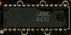 The
TMS1045 is a member of the TMS1040 Product Family based on the
TMS1070
"computer-on-a-chip" introduced in 1974 with the original
TMS1000.
While the TMS1070 can directly interface with low-voltage VFD up to 35 Volts
does it still need external resistors and a zener diode to bias the anodes and
grids of the display with respect to the filament. The TMS1040 added an extra
VPP pin to connect a negative 30 Volts bias voltage for its modified
output drivers. With the TMS1070 featuring 11 R Outputs for the Digits, 8 O
Outputs for the Segments and 4 K Inputs for the Keyboard, reduced the TMS1040
the number of R Outputs to 9, consequently are all known TMS1040 calculator
designs using a 9-digit VF Display.
The
TMS1045 is a member of the TMS1040 Product Family based on the
TMS1070
"computer-on-a-chip" introduced in 1974 with the original
TMS1000.
While the TMS1070 can directly interface with low-voltage VFD up to 35 Volts
does it still need external resistors and a zener diode to bias the anodes and
grids of the display with respect to the filament. The TMS1040 added an extra
VPP pin to connect a negative 30 Volts bias voltage for its modified
output drivers. With the TMS1070 featuring 11 R Outputs for the Digits, 8 O
Outputs for the Segments and 4 K Inputs for the Keyboard, reduced the TMS1040
the number of R Outputs to 9, consequently are all known TMS1040 calculator
designs using a 9-digit VF Display.
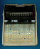
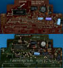 Comparing
the PCB of a Canola L813 manufactured in May 1978 with the PCB of this Canola
L813 II from August 1984 reveals two almost identical designs and we are curious
how Canon managed to change the functionality of the two calculators replacing
the [+/-] and [RM], [CM] keys with [M+], [M-], and [RM/CM] keys. With our DCM-50A Platform
allowing the Characterization of Single-Chip Calculator Circuits
of the TMS1040 Family, we compared the two TMS1045 chips used on the PCBs to
verify that they are 100% identical and the answer is pretty simple: Texas
Instruments offered with most of their TMS1040 designs the calculator
manufacturers a flexible menu to pick the desired functionality, meaning the
chips would support both combined [C/CE] and [R/CM] keys or separate [C][CE] and
[RM][CM] keys and the OEM would chose between them accordingly.
Comparing
the PCB of a Canola L813 manufactured in May 1978 with the PCB of this Canola
L813 II from August 1984 reveals two almost identical designs and we are curious
how Canon managed to change the functionality of the two calculators replacing
the [+/-] and [RM], [CM] keys with [M+], [M-], and [RM/CM] keys. With our DCM-50A Platform
allowing the Characterization of Single-Chip Calculator Circuits
of the TMS1040 Family, we compared the two TMS1045 chips used on the PCBs to
verify that they are 100% identical and the answer is pretty simple: Texas
Instruments offered with most of their TMS1040 designs the calculator
manufacturers a flexible menu to pick the desired functionality, meaning the
chips would support both combined [C/CE] and [R/CM] keys or separate [C][CE] and
[RM][CM] keys and the OEM would chose between them accordingly.
Layout of the Keyboard Matrices with their differences highlighted (Canola L813 and Canola L813 II):
| K1 | K2 | K4 | K8 | V K10 | |
| R0 (D1) | [+420F] | 0 | 6 | +/− | |
| R1 (D2) | [+420F] | 1 | 7 | M−= | |
| R2 (D3) | [+420F] | 2 | 8 | M+= | |
| R3 (D4) | 3 | 9 | |||
| R4 (D5) | [+420F] | 4 | . | ||
| R5 (D6) | 5 | = | |||
| R6 (D7) | %± | CM | RM | RM/CM | |
| R7 (D8) | [Diode] | − | + | ÷ | × |
| R8 (D9) | [ - AM] | CI | C |
Notes: [y z] Sliding Switch Function, y Switch open, z Switch closed. K10 is a "virtual" 5th Keyboard Input line connected with two diodes to the K2 and K8 Keyboard Inputs of the TMS1045NL
If you have additions to the above article please email: joerg@datamath.org.
© Joerg Woerner, December 5, 2001. No reprints without written permission.