DATAMATH CALCULATOR MUSEUM
|
DATAMATH CALCULATOR MUSEUM |
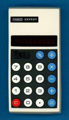
MBO Expert (7C-903)
| Date of introduction: | 1975 | Display technology: | LED-stick |
| New price: | Display size: | 8 + Sign | |
| Size: | 4.6" x
2.4" x 1.0" 116 x 60 x 25 mm3 |
||
| Weight: | 3.0 ounces, 85 grams | Serial No: | 524285 |
| Batteries: | 9V Alkaline | Date of manufacture: | mth 10 year 1975 |
| AC-Adapter: | Origin of manufacture: | Unknown | |
| Precision: | 8 | Integrated circuits: | TMS0833, Bowmar BD5026 |
| Logic: | Chain | Displays: | WB7-44 |
| Memories: | |||
| Program steps: | Courtesy of: | Ken H. Meine |
![]()
 This
MBO Expert was one of the last "four-banger" calculators in decent manufacturing
quality during the heights of the
Calculator Wars in 1975, before products like the
Far East Generic Design I took over.
This
MBO Expert was one of the last "four-banger" calculators in decent manufacturing
quality during the heights of the
Calculator Wars in 1975, before products like the
Far East Generic Design I took over.
MBO International Electronic GmbH, Jena was founded 1973 and started with the MBO
Junior the production of the first portable calculator in Germany. Later MBO
actually placed their nameplates on Far East OEM products.
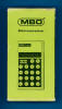
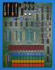
 Dismantling
this MBO Expert calculator manufactured in October 1975 in Asia reveals a clean
design based on a single-sided printed circuit board (PCB) for the main
electronics, a double-sided PCB for the keyboard and powered by a disposable
9-Volt battery.
Dismantling
this MBO Expert calculator manufactured in October 1975 in Asia reveals a clean
design based on a single-sided printed circuit board (PCB) for the main
electronics, a double-sided PCB for the keyboard and powered by a disposable
9-Volt battery.
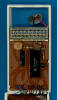 The
Main-PCB is centered around a
TMS0833
single-chip calculator circuit manufactured by Texas Instruments and a
Bowmar
BD5026 Digit Driver chip. The few remaining components on the PCB are mainly used
to generate the clock signal for the internal timing of the TMS0833 and an
additional transistor for the 8th digit of the LED display. Well,
what we wrote here in September 2022 is not exactly accurate. With the featured
MBO Expert calculator being a loaner from our friend Ken, we didn't dig to deep
into it. It is neither a transistor, nor has the display only 8 digits. Learn
more in our most recent update of this page.
The
Main-PCB is centered around a
TMS0833
single-chip calculator circuit manufactured by Texas Instruments and a
Bowmar
BD5026 Digit Driver chip. The few remaining components on the PCB are mainly used
to generate the clock signal for the internal timing of the TMS0833 and an
additional transistor for the 8th digit of the LED display. Well,
what we wrote here in September 2022 is not exactly accurate. With the featured
MBO Expert calculator being a loaner from our friend Ken, we didn't dig to deep
into it. It is neither a transistor, nor has the display only 8 digits. Learn
more in our most recent update of this page.
![]() The
TMS0833 is closely related to the
TMS0800 Product Family and tracing back to
the TMS1802NC, the first available standard calculator building block on a chip,
later renamed into TMS0102. The TMS0800
kept the size of the Instruction ROM (Read-Only Memory), but decreased the Data
Memory from 13 Digits Registers to 11 Digit Registers and added both integrated
Segment Drivers for the LED display and a clock generator.
The
TMS0833 is closely related to the
TMS0800 Product Family and tracing back to
the TMS1802NC, the first available standard calculator building block on a chip,
later renamed into TMS0102. The TMS0800
kept the size of the Instruction ROM (Read-Only Memory), but decreased the Data
Memory from 13 Digits Registers to 11 Digit Registers and added both integrated
Segment Drivers for the LED display and a clock generator.
![]() The
unusual BD5026 display driver located with this MBO Expert manufactured in
October 1975 is a relict of Bowmar's unsuccessful venture as manufacturer of
Integrated Circuits before filing in 1976 for bankruptcy.
The
unusual BD5026 display driver located with this MBO Expert manufactured in
October 1975 is a relict of Bowmar's unsuccessful venture as manufacturer of
Integrated Circuits before filing in 1976 for bankruptcy.
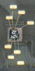
![]() The
display module of the MBO Expert uses nine small LED chips bonded on a substrate
with an additional magnifying lens to enlarge the digits.
The
display module of the MBO Expert uses nine small LED chips bonded on a substrate
with an additional magnifying lens to enlarge the digits.

 Update (August 2024): On our quest to
Record the ROM
Content of the TMS0833 single-chip calculator circuit, we acquired an MBO
Expert in Germany (Thank you, Frank!) and studied its electronic circuitry
completely. Disassembling the donor calculator with serial number #501250 and
manufactured most likely in October 1975, resulted in three surprises:
Update (August 2024): On our quest to
Record the ROM
Content of the TMS0833 single-chip calculator circuit, we acquired an MBO
Expert in Germany (Thank you, Frank!) and studied its electronic circuitry
completely. Disassembling the donor calculator with serial number #501250 and
manufactured most likely in October 1975, resulted in three surprises:
|
• The single transistor has
one pin cut and works as a diode • The display driver with its small 16-pin package is driving the common cathodes of a 9-digit LED display • The three resistors between the LED display and the two Integrated Circuits (ICs) are part of the power supply circuitry |
Calculating Unit: The TMS0833 is a member of the TMS0830 Product Family, introduced in Winter 1974 and closely related to the TMS0800 Product Family, but adopting the low-voltage PMOS process developed for the TMS0950 used with the TI-1200. While the original TMS0800 design is using for VDD and VGG two different power supplies of -10.0 V and -15.8 V, respectively, can the TMS0830 be powered directly with a single 9-Volt battery. One key feature of a PMOS process is its threshold voltage for inputs signals, we measured around -2.6 V on a TMS0801 and less than -1.3 V on a TMS0833.
 With low-cost battery operated LED calculators in mind, Texas
Instruments added a so-called Timeout
feature to the TMS0830 devices. When no key presses are detected for about 20 seconds, the display
blanks out and shows only a '-' in the leftmost digit to reduce power
consumption of the calculator. Looking closely at the printed circuit board (PCB) traces of the donor
MBO Expert, you'll recognize that Pin 10 (WDK) and Pin 8 (KN) are connected to
effectively disable the Timeout feature. The 2-pin "NPN bipolar junction transistor
(BJT)" is acting as a diode to
isolate the KN node of the keyboard matrix from the corresponding TMS0833 input pin. Difficult to understand with the mediocre battery
life of the MBO Expert.
With low-cost battery operated LED calculators in mind, Texas
Instruments added a so-called Timeout
feature to the TMS0830 devices. When no key presses are detected for about 20 seconds, the display
blanks out and shows only a '-' in the leftmost digit to reduce power
consumption of the calculator. Looking closely at the printed circuit board (PCB) traces of the donor
MBO Expert, you'll recognize that Pin 10 (WDK) and Pin 8 (KN) are connected to
effectively disable the Timeout feature. The 2-pin "NPN bipolar junction transistor
(BJT)" is acting as a diode to
isolate the KN node of the keyboard matrix from the corresponding TMS0833 input pin. Difficult to understand with the mediocre battery
life of the MBO Expert.
Display: The MBO Expert donor calculator manufactured around October 1975 makes use of a WB7-44 9-Digit Calculator Numeric 7-Segment LED display module from an unknown manufacturer. It uses nine small 7-Segment displays chips bonded onto a PCB and magnified with a clear plastic lens. The display module is connected with 17 pins to the Main-PCB and follows the pinout of similar displays.

 Display Driver: The Main-PCB of the disassembled MBO
Expert calculator makes use of a BD5026 9-channel digit driver manufactured by Bowmar for the LED display,
while the TMS0833 chip drives the segments directly. Nine digits and a 16-pin
package? Nine inputs, nine outputs and two power supply pins - that doesn't fit
into a 16-pin package! Perhaps not in Dallas, TX, but obviously in
Acton, MA. A closer look at the PCB traces shows only five connections between
the TMS0833 single-chip calculator circuit and the BD5026 digit driver. To
completely understand the magic of the BD5026, we used a simplified breadboard
setup with the chips retrieved from the donor calculator and connected a Logic
Analyzer to all input and output pins. Learn more about the innovative "interpolating"
digit driver technology developed by Bowmar.
Display Driver: The Main-PCB of the disassembled MBO
Expert calculator makes use of a BD5026 9-channel digit driver manufactured by Bowmar for the LED display,
while the TMS0833 chip drives the segments directly. Nine digits and a 16-pin
package? Nine inputs, nine outputs and two power supply pins - that doesn't fit
into a 16-pin package! Perhaps not in Dallas, TX, but obviously in
Acton, MA. A closer look at the PCB traces shows only five connections between
the TMS0833 single-chip calculator circuit and the BD5026 digit driver. To
completely understand the magic of the BD5026, we used a simplified breadboard
setup with the chips retrieved from the donor calculator and connected a Logic
Analyzer to all input and output pins. Learn more about the innovative "interpolating"
digit driver technology developed by Bowmar.
Clock: The MBO Expert makes use of the internal clock oscillator of the TMS0830 chip, we identified a resistor with 200k Ohm connected between Pin 14 (REXT/Clock Select) of the TMS0833 and the negative power supply line, resulting in a clock frequency of about of 82 kHz.
Power Supply: The MBO Expert calculator is powered with a disposable 9-Volt battery and three resistors limit the peak currents of the 9-digit LED display:
|
• A beefy 20 Ohm resistor is
connected between the battery and the negative (VDD) power rail of the
calculator, limiting the overall current • A beefy 39 Ohm resistor is connected between VDD and the negative power supply bin of the BD5026 Digit Driver, limiting the digit currents • A smaller 5.1 Ohm resistor is connected between the positive power rail (VSS) and the TMS0833 Chip, limiting the segment currents |
With all these efforts we expected a very low power consumption of the MBO Expert but measured:
| Mode | Display | Current VBAT = 9.0 V |
Clock Frequency |
| Calculating | 0. | 13 mA | 82 kHz |
| Calculating | 88888888. | 56 mA | 82 kHz |
Calculating the power consumption at 9 Volts for the MBO Expert results in about 120 mW displaying a '0.' and about 500 mW with all segments but the minus sign illuminated. A Canon LE-84 calculator using four disposable 1.5 Volt Alkaline batteries and a DC/DC converter for its TMS0801 chip clocks in at around 100 mW and 320 mW, respectively. A fresh 9-Volt Alkaline battery would last around 10 to 30 hours in the MBO Expert calculator, while 4 AA-sized Alkaline batteries would power the Canon LE-84 up to 100 hours. At first glance might these numbers be astonishing, but they are easy to explain with Kirchhoff's second rule (the loop rule). In a closed loop, whatever energy is supplied by a voltage source, the energy must be transferred into other forms by the devices in the loop. Kirchhoff's loop rule states that the algebraic sum of all potential differences, including the voltage sources, in any loop must be zero.
With the numbers from our donor MBO Expert, we calculate in a first step the average current per segment. The differences between the '0.' and '88888888.' displays are 50 segments and 43 mA, or 0.86 mA per segment. The TMS0833 chip is scanning the digits and segments with a 1:10 duty cycle, resulting in 8.6 mA average segment current per Digit Time. Each Digit Time has 11 State Times with S1 and S11 blanking the segments for a peak current of 10.5 mA per segment and around 80 mA per digit. The high-efficiency LED chips used with the calculator have a voltage drop of around 1.7 V at 10 mA segment current, and with a 9-Volt battery the sum of all other components in the loop will "burn" around 7.2 V:
| • 5.1 Ohm resistor (0.4 V) - TMS0833 segment driver (1.8 V) - LED chip (1.7 V) - BD5026 digit driver (0.3 V) - 39 Ohm resistor (3.2 V) - 20 Ohm resistor (1.6 V) |
The Canon LE-84 calculator on the other hand is using four 1.5 Volt batteries in series for the LED driver circuitry and consequently needs to "burn" just around 4 V between power supply and LED chips. And the true master is Texas Instruments with its TI-2500-II design, using only two 1.5 Volt batteries and "burning" just 1 V between power supply and LED chips.

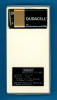
 Keyboard: The keyboard assembly of the MBO Expert uses
spring-supported plastic keys pushing a small copper element against
a pin soldered onto a double-sided phenolic PCB combining both long-travel
keys with reasonable manufacturing costs while maintaining longevity of the
calculator. The keyboard module is connected with 14 short wires to
the Main-PCB.
Keyboard: The keyboard assembly of the MBO Expert uses
spring-supported plastic keys pushing a small copper element against
a pin soldered onto a double-sided phenolic PCB combining both long-travel
keys with reasonable manufacturing costs while maintaining longevity of the
calculator. The keyboard module is connected with 14 short wires to
the Main-PCB.
 With
the DCM-50A Platform developed to
Characterize and
Reverse-engineer
Single-chip Calculator Circuits we could proof that the TMS0833 uses the same
Program Code as the TMS0803 known from the
TI-1500 or
TI-2550-II.
With
the DCM-50A Platform developed to
Characterize and
Reverse-engineer
Single-chip Calculator Circuits we could proof that the TMS0833 uses the same
Program Code as the TMS0803 known from the
TI-1500 or
TI-2550-II.
If you have additions to the above article please email: joerg@datamath.org.
© Joerg Woerner, September 6, 2022. No reprints without written permission.