DATAMATH CALCULATOR MUSEUM
|
DATAMATH CALCULATOR MUSEUM |
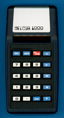
Model 1000
| Date of introduction: | 1973 | Display technology: | LED |
| New price: | Display size: | 8 + 1 | |
| Size: | 6.0" x 3.1 x 1.0" 152 x 80 x 25 mm3 |
||
| Weight: | 4.6 ounces, 129 grams | Serial No: | 80-09690 |
| Batteries: | 9V | Date of manufacture: | mth 10 year 1973 |
| AC-Adapter: | Origin of manufacture: | USA | |
| Precision: | 8 | Integrated circuits: | AMI S2144, ITT 492, Fairchild SL23557 |
| Logic: | Chain | Displays: | |
| Memories: | |||
| Program steps: | Courtesy of: | Joerg Woerner |
![]()
 If
we trace back the history of Melcor
we locate the rare Mariner NRC 7200 as starting point
of their calculator business. The NRC 7200 was introduced already in December 1971
and looks similar to the Bowmar 901B. Both
designs used mainly technology and components from Texas Instruments, e.g. the
calculator chip, keyboard, display drivers and even the display. In 1972 TI
started their manufacturing of calculators and consequently changed their
perspective for Bowmar and
Melcor from component manufacturing to competitor. As a logical result
a lot of "TI-free" calculators appeared. This Model 1000 uses:
If
we trace back the history of Melcor
we locate the rare Mariner NRC 7200 as starting point
of their calculator business. The NRC 7200 was introduced already in December 1971
and looks similar to the Bowmar 901B. Both
designs used mainly technology and components from Texas Instruments, e.g. the
calculator chip, keyboard, display drivers and even the display. In 1972 TI
started their manufacturing of calculators and consequently changed their
perspective for Bowmar and
Melcor from component manufacturing to competitor. As a logical result
a lot of "TI-free" calculators appeared. This Model 1000 uses:
| • Keyboard technology from
an unknown OEM • A calculator chip from American Microsystems, Inc (AMI) • A display manufactured by an unknown OEM • Display drivers made by Fairchild and ITT |

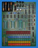
 Dismantling
this Melcor Model 1000 calculator manufactured in October 1973 in the United
States reveals a very innovative design using a single-sided printed circuit
board (PCB) centered around an AMI S2144
single-chip calculator circuit connected to a 9-digit LED display, a keyboard
assembly and powered by a 9V alkaline battery. A very prominent feature of the
Melcor Model 1000 calculator are the two [ON] and [OFF] buttons instead the
common sliding or rocker switches found in other calculators designed in 1973 to
turn the calculator on and off.
Dismantling
this Melcor Model 1000 calculator manufactured in October 1973 in the United
States reveals a very innovative design using a single-sided printed circuit
board (PCB) centered around an AMI S2144
single-chip calculator circuit connected to a 9-digit LED display, a keyboard
assembly and powered by a 9V alkaline battery. A very prominent feature of the
Melcor Model 1000 calculator are the two [ON] and [OFF] buttons instead the
common sliding or rocker switches found in other calculators designed in 1973 to
turn the calculator on and off.
![]()
![]() The featured Model 1000
calculator uses a Nine-Digit Calculator Numeric Seven-Segment LED Displays
manufactured by an unknown OEM and mounted directly on the Main-PCB and
controlled with two integrated digit drivers and the 8 segments driven directly
from the AMI S2144 calculator chip. The other components on the PCB are used for
the power supply of the S2144, its clock generator, detection of a low-voltage
situation of the 9V battery and the already mentioned electronic power
on/off-circuitry. And in case you wonder about the unusual [PD] key, it is used
to set the calculator chip either in fixed-point [DP][0...7] or floating-point
[DP][.] mode for the number display.
The featured Model 1000
calculator uses a Nine-Digit Calculator Numeric Seven-Segment LED Displays
manufactured by an unknown OEM and mounted directly on the Main-PCB and
controlled with two integrated digit drivers and the 8 segments driven directly
from the AMI S2144 calculator chip. The other components on the PCB are used for
the power supply of the S2144, its clock generator, detection of a low-voltage
situation of the 9V battery and the already mentioned electronic power
on/off-circuitry. And in case you wonder about the unusual [PD] key, it is used
to set the calculator chip either in fixed-point [DP][0...7] or floating-point
[DP][.] mode for the number display.
![]()
![]() On our quest to fully understand the features of the rare AMI S2144 chip used
with only a few other known calculators like the RFT minirex 74, we
decided to completely reverse-engineer the PCB of the Melcor Model 1000 on a
component level. One of the interesting findings is the use of two different,
yet pin-compatible "SN75492-style" 6-channel
digit
drivers for the LED display and we learned that the ITT 492 driver at position
A2 controls the five right-most digits while the Fairchild SL23557 driver at
position A3 controls the four left-most digits and has one of the remaining
input pins connected to the center tap of a potentiometer and the corresponding
output connected to an input pin of the AMI S2144. Obviously not the intended use
of a "digit driver" for LED displays and probably the reason to use the SL23557
chip in position A3. Evaluating the functionality of the PCB schematics reveals
that this part of the circuitry is used as a simple "under-voltage" detection of
the 9V battery signaled by the S2144 on the left-most decimal point of the
display.
On our quest to fully understand the features of the rare AMI S2144 chip used
with only a few other known calculators like the RFT minirex 74, we
decided to completely reverse-engineer the PCB of the Melcor Model 1000 on a
component level. One of the interesting findings is the use of two different,
yet pin-compatible "SN75492-style" 6-channel
digit
drivers for the LED display and we learned that the ITT 492 driver at position
A2 controls the five right-most digits while the Fairchild SL23557 driver at
position A3 controls the four left-most digits and has one of the remaining
input pins connected to the center tap of a potentiometer and the corresponding
output connected to an input pin of the AMI S2144. Obviously not the intended use
of a "digit driver" for LED displays and probably the reason to use the SL23557
chip in position A3. Evaluating the functionality of the PCB schematics reveals
that this part of the circuitry is used as a simple "under-voltage" detection of
the 9V battery signaled by the S2144 on the left-most decimal point of the
display.

 Update (August 2024): We
measured the Output Voltage vs Input Voltage of both the Fairchild SL23557 and
ITT 492 devices to retrieve their "Signature"
and noticed that the SL23557 has a lower threshold voltage and a higher gain
than the ITT 492.
Update (August 2024): We
measured the Output Voltage vs Input Voltage of both the Fairchild SL23557 and
ITT 492 devices to retrieve their "Signature"
and noticed that the SL23557 has a lower threshold voltage and a higher gain
than the ITT 492.
 Understanding the schematic diagrams of both the Melcor Model 1000 and an RFT
minirex 74 calculator demonstrated the compatibility of the AMI S2144 with our DCM-50A Platform
and we were able to operate it in the right-most TMS1000 Textool Test Socket
with some extra patches, hence allowing us to go through our process of
Characterization of Single-Chip Calculator Circuits.
Understanding the schematic diagrams of both the Melcor Model 1000 and an RFT
minirex 74 calculator demonstrated the compatibility of the AMI S2144 with our DCM-50A Platform
and we were able to operate it in the right-most TMS1000 Textool Test Socket
with some extra patches, hence allowing us to go through our process of
Characterization of Single-Chip Calculator Circuits.
If you have additions to the above article please email: joerg@datamath.org.
© Joerg Woerner, February 5, 2023. No reprints without written permission.