DATAMATH CALCULATOR MUSEUM
|
DATAMATH CALCULATOR MUSEUM |
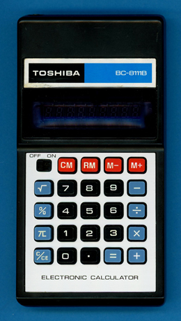
Toshiba BC-8111B
| Date of introduction: | 1979 | Display technology: | Fluorescent |
| New price: | DM 25.00 | Display size: | 8 |
| Size: | 5.6" x 3.0" x 0.8" 142 x 75 x 20 mm3 |
||
| Weight: | 3.9 ounces, 110 grams | Serial No: | C 17661 |
| Batteries: | 2*AA | Date of manufacture: | mth 01 year 1979 |
| AC-Adapter: | BH-115 (110V) or BH-116 (220V) |
Origin of manufacture: | Taiwan |
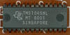
| Precision: | 8 | Integrated circuits: | TMS1045 (MT 8001) |
| Memories: | 1 | Displays: | Futaba 9-ST-08A |
| Program steps: | Courtesy of: | Joerg Woerner |
![]()
![]() This
Toshiba BC-8111B "Basic with Memory" calculator followed the otherwise identical
BC-8111 and shares its internal design with
the BC-8018B "Basic" and
BC-8112SL "Enhanced Basic" calculators. The rather unusual
approach to use identical electronics for three calculators with a quite
different feature set was made possible with Texas Instruments' introduction of
the cost-effective TMS1040 Product Family based on the
TMS1070
"computer-on-a-chip" introduced in 1974 with the original
TMS1000.
But we have to credit Canon releasing the full potential of the TMS1040 with its
"Almost Scientific" F-31 calculator in 1977.
This
Toshiba BC-8111B "Basic with Memory" calculator followed the otherwise identical
BC-8111 and shares its internal design with
the BC-8018B "Basic" and
BC-8112SL "Enhanced Basic" calculators. The rather unusual
approach to use identical electronics for three calculators with a quite
different feature set was made possible with Texas Instruments' introduction of
the cost-effective TMS1040 Product Family based on the
TMS1070
"computer-on-a-chip" introduced in 1974 with the original
TMS1000.
But we have to credit Canon releasing the full potential of the TMS1040 with its
"Almost Scientific" F-31 calculator in 1977.
Comparing the functionality of the three Toshiba calculators and the Canon F-31 demonstrates the bandwidth of products made possible with the TMS1045 single-chip calculator circuit:
| Calculator | M+ | +/- | 1/x | x2 | √x | % | PI | () | 2-0-F |
| Toshiba BC-8018B | * | * | * | ||||||
| Toshiba BC-8111B | * | * | * | * | |||||
| Toshiba BC-8112SL | * | * | * | * | * | * | * | ||
| Canon F-31 | * | * | * | * | * | * | * | * | * |
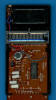
 Dismantling
the featured BC-8111B calculator manufactured in January 1980 by
Zeny Corporation in Taiwan
reveals a very cost effective design using a single-sided printed circuit board
(PCB) centered around a TMS1045 single-chip calculator circuit connected to a 9-digit
Vacuum Fluorescent Display (VFD), a keyboard assembly and powered by 2 AA-sized
alkaline batteries.
Dismantling
the featured BC-8111B calculator manufactured in January 1980 by
Zeny Corporation in Taiwan
reveals a very cost effective design using a single-sided printed circuit board
(PCB) centered around a TMS1045 single-chip calculator circuit connected to a 9-digit
Vacuum Fluorescent Display (VFD), a keyboard assembly and powered by 2 AA-sized
alkaline batteries.
![]()
 While the
earlier TMS1070 can directly interface with low-voltage VFD up to 35 Volts
does it still need external resistors and a zener diode to bias the anodes and
grids of the display with respect to the filament. The TMS1040 added an extra
VPP pin to connect a negative 30 Volts bias voltage for its modified
output drivers. With the TMS1070 featuring 11 R Outputs for the Digits, 8 O
Outputs for the Segments and 4 K Inputs for the Keyboard, reduced the TMS1040
the number of R Outputs to 9, consequently are all known TMS1040 calculator
designs using a 9-digit VF Display.
While the
earlier TMS1070 can directly interface with low-voltage VFD up to 35 Volts
does it still need external resistors and a zener diode to bias the anodes and
grids of the display with respect to the filament. The TMS1040 added an extra
VPP pin to connect a negative 30 Volts bias voltage for its modified
output drivers. With the TMS1070 featuring 11 R Outputs for the Digits, 8 O
Outputs for the Segments and 4 K Inputs for the Keyboard, reduced the TMS1040
the number of R Outputs to 9, consequently are all known TMS1040 calculator
designs using a 9-digit VF Display.
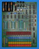 Looking
closer onto the PCB you'll notice two diodes labeled D4 and D5 and placed
somehow between the TMS1045 and the keyboard assembly - at first glance an unusual
approach. Preparing our DCM-50A Platform
to allow the Characterization of Single-Chip Calculator Circuits
of the TMS1040 Family, we reverse-engineered the BC-8111B calculator and
understood that Texas Instruments started to add with the TMS1040 a "virtual"
5th Keyboard Input line by using two additional diodes emulating the 5 K Inputs
of the TMC0980 Family. While the
TMS0100 single-chip calculator circuit
introduced the concept of an 11x4 keyboard matrix scanned with the 11 Digit
Outputs and 4 Keyboard Inputs, would the reduction to just 9 Digit Outputs of
the TMS1040 allow for only 9x4 keys and switches, in some calculator
applications like the Canon F-31 a show-stopper. Adding an extra "virtual" Keyboard
Input allows consequently for a 9x5 keyboard matrix and this BC-8111B arranges its
24 keys within a 9x4 grid.
Looking
closer onto the PCB you'll notice two diodes labeled D4 and D5 and placed
somehow between the TMS1045 and the keyboard assembly - at first glance an unusual
approach. Preparing our DCM-50A Platform
to allow the Characterization of Single-Chip Calculator Circuits
of the TMS1040 Family, we reverse-engineered the BC-8111B calculator and
understood that Texas Instruments started to add with the TMS1040 a "virtual"
5th Keyboard Input line by using two additional diodes emulating the 5 K Inputs
of the TMC0980 Family. While the
TMS0100 single-chip calculator circuit
introduced the concept of an 11x4 keyboard matrix scanned with the 11 Digit
Outputs and 4 Keyboard Inputs, would the reduction to just 9 Digit Outputs of
the TMS1040 allow for only 9x4 keys and switches, in some calculator
applications like the Canon F-31 a show-stopper. Adding an extra "virtual" Keyboard
Input allows consequently for a 9x5 keyboard matrix and this BC-8111B arranges its
24 keys within a 9x4 grid.
If you have additions to the above article please email: joerg@datamath.org.
© Joerg Woerner, July 3, 2002. No reprints without written permission.