DATAMATH CALCULATOR MUSEUM
|
|
DATAMATH CALCULATOR MUSEUM |
Characterization of Single-chip Calculator Circuits - Other Devices
The DCM-50A Platform supports the Characterization of the S2144 Device with the TMS1000 Textool Test Socket set to DCM-50A (TMS1000) mode and patching (swapping) most of the pins. One additional patch wire is needed to connect the external clock oscillator not available on the TMS1000 Socket but on the TMS0100 Socket or directly through the Digilent Digital Discovery Interface. The voltages VSS and VGG are set to 6.5V and -3.5V, respectively and VDD is patched to the TMS0800 Socket.
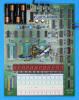
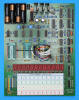
![]() Device-under-Test:
Device-under-Test:
| • Package Markings Top
(Upside down): AMI 7333KEO, S2144 • Package Markings Bottom: NONE • Donor Calculator: Melcor Model 1000, October 1973 |
Keyboard: The Melcor Model 1000 makes use of a keyboard with 18 of its 20 switches arranged in an 9*2 matrix with the rows connected to the D1 to D9 Outputs (Display Scan) and the columns connected to the KN and KO Inputs (Keyboard Scan) of the S2144 single-chip calculator circuit. The [ON] and [OFF] keys are used with additional electronics to replace a traditional sliding switch.
Keyboard Matrix of the Melcor Model 1000:
| KN | KO | |
| D1 | 1 | × |
| D2 | 2 | ÷ |
| D3 | 3 | PD |
| D4 | 4 | + |
| D5 | 5 | − |
| D6 | 6 | = |
| D7 | 7 | C/CE |
| D8 | 8 | 0 |
| D9 | 9 | . |
![]() Display: The
Melcor Model 1000 makes use of an unknown Nine-Digit Calculator Numeric
Seven-Segment LED Display module controlled with 2 additional
SN75492-style
digit drivers from the corresponding Output pins D1 to D9 and the segments SA to
SDP driven directly from the S2144 chip.
Display: The
Melcor Model 1000 makes use of an unknown Nine-Digit Calculator Numeric
Seven-Segment LED Display module controlled with 2 additional
SN75492-style
digit drivers from the corresponding Output pins D1 to D9 and the segments SA to
SDP driven directly from the S2144 chip.
Display Layout:
| Nine-Digit LED Module |
|
|
The Output Decoder of the S2144 is programmed for 7-Segment displays with the following Output Assignments:
| S2144 Pin | 23 | 24 | 25 | 26 | 27 | 28 | 2 | 22 |
| Segment | A | B | C | D | E | F | G | DP |
| The Segment drivers A-G and DP (Decimal Point) are connected to the Nine-Digit LED display in the pictured way. | 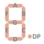 |
Display Fonts:
| Type | Calculator | Number Fonts | Decimal Separator |
Thousands Separator |
Entry Overflow |
Calculating Overflow |
Minus | Memory Indicator |
| AMI S2144 | Melcor 1000 | n.a. | n.a. |
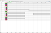
 Scanning: Display and keyboard scanning is performed in
D1 → D9 direction at a rate of about 1,250 Hz
with one Blank State after D9:
Scanning: Display and keyboard scanning is performed in
D1 → D9 direction at a rate of about 1,250 Hz
with one Blank State after D9:
|
• Instruction Cycle Time
(ICT) = 1 Clock = 0.02 ms @ CK=50 kHz • Leading Digit Blanking Time = 0.5 ICT = 0.01 ms • Active Digit Time = 3 ICT = 0.06 ms • Trailing Digit Blanking = 0.5 ICT = 0.01 ms • Blank State D9 → D1 = 4 ICT = 0.08 ms • Display Cycle Time = 40 ICT = 0.8 ms |
The DCM-50A Platform supports the Characterization of Mostek MK5020 Product Family Devices with the TMS1000 Textool Test Socket set to DCM-50A (TMS1000) mode and patching (swapping) most of the pins. One additional patch wire is needed to connect the Segment H output not available on the TMS1000 Socket but on the TMS0100 Socket and an additional "pull-down" resistor is necessary for the Clock Output pin of the MK5020 chip. The voltages VSS and VDD/VGG are set to 9.5V and -5.5V, respectively. Alternatively the MK5020 chip can be placed in the TMS0100 Textool Test Socket set to DCM-50A (TMS0100) mode and Pin 14 isolated.
![]() Device-under-Test:
Device-under-Test:
| • Package Markings Top:
MOSTEK, MK5020A, ASSY IN KOR., 7342 H • Package Markings Bottom: NONE • Donor Calculator: Heathkit IC-2006, November 1973 |
Keyboard: The Heathkit IC-2006 makes use of a keyboard with 17 switches arranged in an 11*2 matrix with the rows connected to the D1-D11 Outputs (Display Scan) and the columns connected to the KN and KO Inputs (Keyboard Scan) of the MK5020A single-chip calculator circuit. The Constant/Chain sliding switch is connected between D10-KQ.
Keyboard Matrix of the Heathkit IC-2006:
| KN | KO | KP | KQ | |
| D1 | 1 | |||
| D2 | 2 | × | ||
| D3 | 3 | ÷ | ||
| D4 | 4 | |||
| D5 | 5 | += | ||
| D6 | 6 | −= | ||
| D7 | 7 | |||
| D8 | 8 | |||
| D9 | 9 | . | ||
| D10 | 0 | CE | K | |
| D11 | C |
![]() Display: The
Heathkit IC-2006 makes use of 3 National Semiconductor NSN33 Three-Digit
Calculator Numeric Seven-Segment LED Displays mounted directly on the Main-PCB
and controlled with 9 discrete digit drivers and 8 discrete segment drivers from
the corresponding Output pins D1 to D9 and SA to SDP of the MK5020A chip with SH
not connected.
Display: The
Heathkit IC-2006 makes use of 3 National Semiconductor NSN33 Three-Digit
Calculator Numeric Seven-Segment LED Displays mounted directly on the Main-PCB
and controlled with 9 discrete digit drivers and 8 discrete segment drivers from
the corresponding Output pins D1 to D9 and SA to SDP of the MK5020A chip with SH
not connected.
Display Layout:
| 3*NSN33 |
|
|
The Output Decoder PLA of the MK5020A is programmed for 7-Segment displays with the following Output Assignments:
| MK5020A Pin | 16 | 17 | 18 | 19 | 20 | 21 | 22 | 23 | 24 |
| Segment | A | B | C | D | E | F | G | H | DP |
| The Segment drivers A-G and DP (Decimal Point) are connected to the 3*NSN33 display in the pictured way. | |
Display Fonts:
| Type | Calculator | Number Fonts | Decimal Separator |
Thousands Separator |
Entry Overflow |
Calculating Overflow |
Minus | Memory Indicator |
| MK5020A | Heathkit IC-2006 | n.a. | n.a. |

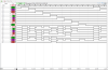
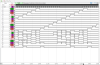 Scanning: Display and keyboard scanning is performed in
D11 → D1 direction at a rate of about 350 Hz:
Scanning: Display and keyboard scanning is performed in
D11 → D1 direction at a rate of about 350 Hz:
|
• Instruction Cycle Time
(ICT) = 3 Clocks = 0.02 ms @ CK=150 kHz • Leading Digit Blanking Time = 1 ICT = 0.02 ms • Active Digit Time = 11 ICT = 0.22 ms • Trailing Digit Blanking = 1 ICT = 0.02 ms • Display Cycle Time = 143 ICT = 2.86 ms |
The DCM-50A Platform supports the Characterization of the TMS3878 Five Decade Counter and the closely related TMS3707 with some supporting circuitry and the TMS1000 Textool Test Socket set to DCM-50A (TMS1000) mode. We added on a small breadboard a 10.24 MHz crystal oscillator with a 5-bit frequency divider to generate the 320 kHz time base clock of the TMS3707, a 6 MHz crystal oscillator with a 4-bit frequency divider to generate test frequencies between 375 kHz and 6 MHz, a 4-bit prescaler for the pulse input pin of the TMC3707 and a voltage regulator to generate the necessary VDD voltage of -5V. The voltages VSS and VDD/VGG at the TMS1000 Textool Test Socket are set to their lowest voltages of 5.5V and -3.0V, respectively.

 Device-under-Test:
| • Package Markings Top:
TMS3707NC, y 8107 • Package Markings Bottom: GERMANY G6 • Donor Product: NIB, February 1981 |
Keyboard: The TMS3707NC is in its known applications not connected to a keyboard.
Display: The Philips AM/FM car radios Coupé Digital 890 and 894 (22AC890, 22AC894) are using a green 3½-digit Sanyo SL-2405 LED display while the TMS3707 is supporting 5-digit LED displays.
Display Layout:
| SANYO SL-2405 |
|
|
The Output Decoder PLA of the TMS3707 is programmed for 7-Segment displays with the following Output Assignments:
| TMS3707 Pin | 12 | 11 | 10 | 9 | 8 | 7 | 6 | 5 |
| Segment | A | B | C | D | E | F | G | DP |
| The Segment drivers A-G and DP (Decimal Point) are connected to the SL-2405 display in the pictured way. | |
Display Fonts:
| Type | Product | Number Fonts | Decimal Separator |
| TMS3707NC | Philips 22AC890 |


 Scanning: Display scanning is performed in
D1 → D5 direction with an Active Digit Time of 3.3 ms and a Blanking Time
of 0.1 ms at a rate of about 60 Hz. The Segments A to G and the Decimal Point
have an Active Segment Time of 2.4 ms and are activated in a staggered timing of 0.1 ms steps:
Scanning: Display scanning is performed in
D1 → D5 direction with an Active Digit Time of 3.3 ms and a Blanking Time
of 0.1 ms at a rate of about 60 Hz. The Segments A to G and the Decimal Point
have an Active Segment Time of 2.4 ms and are activated in a staggered timing of 0.1 ms steps:
|
• Main Clock Cycle
(MCC) = 32 Clocks = 0.1 ms @ CK=320 kHz • Active Digit Time = 33 MCC = 3.3 ms • Digit Blanking = 1 MCC = 0.1 ms • Display Cycle Time = 34 MCC = 3.4 ms |
If you have additions to the above article please email: joerg@datamath.org.
© Joerg Woerner, February 4, 2023. No reprints without written permission.