DATAMATH CALCULATOR MUSEUM
|
DATAMATH CALCULATOR MUSEUM |
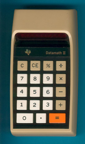
Texas Instruments TI-2500-II / Datamath II
| Date of introduction: | November 11, 1974 | Display technology: | LED-stick |
| New price: | $49.95, DM 148.00 | Display size: | 8 + Sign |
| Size: | 5.5" x 3.0" x 1.7" 139 x 76 x 42 mm3 |
||
| Weight: | 6.7 ounces, 191 grams | Serial No: | 2500-II-256861 |
| Batteries: | 2*AA NiCd or 2*AA Alkaline | Date of manufacture: | wk 32 year 1975 |
| AC-Adapter: | AC9130 | Origin of manufacture: | USA |
| Precision: | 8 | Integrated circuits: | TMS0803, SN27882 or SN75498 |
| Logic: | Chain | Displays: | DIS206C |
| Memories: | |||
| Program steps: | Courtesy of: | Joerg Woerner | |
| Download manual: | |
![]() The
Datamath II alias TI-2500-II is a quite funny calculator. It uses the modern
electronics of the stylish TI-1500 calculator in the old-fashioned
Datamath
housing. It was introduced late and never a big success.
The
Datamath II alias TI-2500-II is a quite funny calculator. It uses the modern
electronics of the stylish TI-1500 calculator in the old-fashioned
Datamath
housing. It was introduced late and never a big success.
The main difference to the other Datamath calculators is the
added [%] key and the usage of only 2 rechargeable NiCd batteries. Take a look on
the Version 1 of the Datamath!
A more detailed comparison between the ten known Datamath Versions could be found here.
The Datamath II seems to be together with the TI-150 the last TI calculator using the standard Klixon™ keyboard technology.
In Spain this calculator was labeled TI-2500 II without the dash at the series II designation.
 Ken Shirriff studied the United
States Patent Application
US3934233A
describing the TMS0800 architecture and the program code used with the
TI-1500 very carefully and was
able to create a JavaScript Simulator
for the TMS0800 simulating a (slightly modified)
TI-2500-II.
Ken Shirriff studied the United
States Patent Application
US3934233A
describing the TMS0800 architecture and the program code used with the
TI-1500 very carefully and was
able to create a JavaScript Simulator
for the TMS0800 simulating a (slightly modified)
TI-2500-II.


 Update (August 2024): On our quest to
Record the ROM
Content of the TMS0803 single-chip calculator circuit, we salvaged a
TI-2500-II and studied its electronic circuitry
completely. Disassembling the donor calculator with serial number #058376 and
manufactured in January 1975, resulted in three surprises:
Update (August 2024): On our quest to
Record the ROM
Content of the TMS0803 single-chip calculator circuit, we salvaged a
TI-2500-II and studied its electronic circuitry
completely. Disassembling the donor calculator with serial number #058376 and
manufactured in January 1975, resulted in three surprises:
|
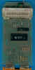
• The printed circuit board
of the TI-2500-II is prepared for a 9-channel digit driver but uses a
7-channel device and two transistors for the remaining channels • The display driver is operated outside of its specifications when using NiCd batteries • The TMS0803 single-chip calculator circuit is operating in slow motion with a clock frequency of just 80 kHz |
![]() Calculating Unit: The TMS0803 is a member of the
TMS0800 Product Family and tracing back to
the TMS1802NC, the first available standard calculator building block on a chip,
later renamed into TMS0102. The TMS0800
kept the size of the Instruction ROM (Read-Only Memory), but decreased the Data
Memory from 13 Digits Registers to 11 Digit Registers and added both integrated
segment drivers for the LED display and a clock generator.
Calculating Unit: The TMS0803 is a member of the
TMS0800 Product Family and tracing back to
the TMS1802NC, the first available standard calculator building block on a chip,
later renamed into TMS0102. The TMS0800
kept the size of the Instruction ROM (Read-Only Memory), but decreased the Data
Memory from 13 Digits Registers to 11 Digit Registers and added both integrated
segment drivers for the LED display and a clock generator.
With low-cost battery operated LED calculators in mind, Texas Instruments added a so-called Timeout feature to the TMS0800 devices. When no key presses are detected for about 20 seconds, the display blanks out and shows only a '-' in the leftmost digit to reduce power consumption of the calculator. Looking closely at the printed circuit board (PCB) traces of the TI-2500-II, you'll recognize that Pin 10 (WDK) and Pin 6 (KP) are connected to effectively disable the Timeout feature.
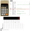
![]() Display: The TI-2500-II calculator manufactured
in January 1975 makes use of a TI206C 9-Digit display module with nine 7-Segment displays chips bonded onto a PCB and magnified with a clear plastic lens. The display module is connected with 17 pins to the Main-PCB
and follows the industry standard pinout.
Display: The TI-2500-II calculator manufactured
in January 1975 makes use of a TI206C 9-Digit display module with nine 7-Segment displays chips bonded onto a PCB and magnified with a clear plastic lens. The display module is connected with 17 pins to the Main-PCB
and follows the industry standard pinout.
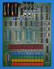
![]() Display Driver: The PCB of the disassembled TI-2500-II calculator makes use of an
SN27882 7-channel digit driver manufactured by
Texas Instruments for the LED display,
while the TMS0803 chip drives the segments directly. The two remaining digit
driver channels are realized with discrete NPN bipolar junction transistors
(BJTs). The specification of the
SN27882 states a minimum VCC voltage of 2.7 Volt, the PCB of the TI-2500-II (and
our measurements) show that the chip is operated with voltages around 2.5 Volt
when using the internal NiCd batteries instead of Alkaline batteries. The layout of the
TI-2500-II is prepared to accommodate an integrated 9-channel digit driver, but
we assume that the part was early in 1975 not yet available. With the digit drivers operated
close to the most positive supply voltage levels (VSS) of the TMS0803 chip,
engineers needed to add pull-down resistors to the negative voltage (VDD) to
allow for an appropriate keyboard scanning. This explains why the inputs of the
SN27882 are specified for input voltages between -8.5 V and 0 V (most negative
VDD voltage is -10.5 V, two completely depleted NiCd batteries would get the
negative supply voltage of the SN27882 to around -2.0 V.
Display Driver: The PCB of the disassembled TI-2500-II calculator makes use of an
SN27882 7-channel digit driver manufactured by
Texas Instruments for the LED display,
while the TMS0803 chip drives the segments directly. The two remaining digit
driver channels are realized with discrete NPN bipolar junction transistors
(BJTs). The specification of the
SN27882 states a minimum VCC voltage of 2.7 Volt, the PCB of the TI-2500-II (and
our measurements) show that the chip is operated with voltages around 2.5 Volt
when using the internal NiCd batteries instead of Alkaline batteries. The layout of the
TI-2500-II is prepared to accommodate an integrated 9-channel digit driver, but
we assume that the part was early in 1975 not yet available. With the digit drivers operated
close to the most positive supply voltage levels (VSS) of the TMS0803 chip,
engineers needed to add pull-down resistors to the negative voltage (VDD) to
allow for an appropriate keyboard scanning. This explains why the inputs of the
SN27882 are specified for input voltages between -8.5 V and 0 V (most negative
VDD voltage is -10.5 V, two completely depleted NiCd batteries would get the
negative supply voltage of the SN27882 to around -2.0 V.
Clock: The TI-2500-II makes use of the internal clock oscillator of the TMS0800 chip, we identified a resistor with 180k Ohm connected between Pin 14 (REXT/Clock Select) of the TMS0803 and the VDD power supply line, resulting in a clock frequency of about of 80-85 kHz.
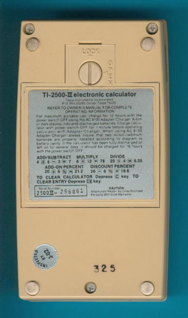
Power Supply: The TI-2500-II reuses the housing of the TI-2500B with its large battery compartment for four AA-sized batteries, but applies a different arrangement to the individual slots. The upper two positions are used with two rechargeable NiCd batteries, while the lower two positions are used for two disposable Alkaline batteries. A small switch detect the presence of disposable batteries and disconnects a possibly attached AC charger. The Main-PCB hosts a power converter circuit centered around an astable multivibrator, step-up transformer, diodes and capacitors to generate the VDD and VGG supply voltages for the TMS0803 chip. We observed on our salvaged TI-2500-II manufactured in January 1975 voltages of VDD = -9.5 V and VGG = -16.8 V while operated with VBAT = 3.0 V, and about VDD = -9.0 V and VGG = -16.0 V while operated with VBAT = 2.5 V. The current consumption was measured with a well-regulated DC power supply attached to the lower contacts of the battery compartment:
| Mode | Display | Current VBAT = 3.0 V |
Clock Frequency |
| Calculating | 0. | 47 mA | 82 kHz |
| Calculating | 88888888. | 123 mA | 82 kHz |
When using its two internal NiCd batteries, the supply voltage of the calculator depends on the charging status, we measured around 2.9 Volt during charging and around 2.5 Volt with the charger unplugged. While running these measurements, we noticed a great fluctuation of the LED display brightness and consequently expected a reduced power consumption at 2.5 Volt applied to the upper contacts of the battery compartment:
| Mode | Display | Current VBAT = 2.5 V |
Clock Frequency |
| Calculating | 0. | 42 mA | 85 kHz |
| Calculating | 88888888. | 90 mA | 85 kHz |
The average current per LED digit drops from about 11 mA at 3.0 V to only 7 mA at 2.5 V, resulting in enough change of the luminous intensity of the LED chips for our human eyes to perceive the difference. Calculating the power consumption at 3 Volt for the TI-2500-II results in about 150 mW displaying a '0.' and about 370 mW with all segments but the minus sign illuminated. A Canon LE-84 calculator with the similar TMS0801 chip and using four disposable 1.5 Volt Alkaline batteries clocks in at around 100 mW and 320 mW, respectively. Simulating the TI-2500-II operated with its rechargeable NiCd batteries on the other hand, results in a power consumption at 2.5 Volt of only 100 mW and 225 mW, respectively.
 Keyboard: The keyboard assembly of the
of the TI-2500-II uses the proved Klixon™
hermetic miniature and sub-miniature snap action switches developed already in
1960. The Keyboard-PCB is connected with 14 stamped metal connectors to
the Main-PCB.
Keyboard: The keyboard assembly of the
of the TI-2500-II uses the proved Klixon™
hermetic miniature and sub-miniature snap action switches developed already in
1960. The Keyboard-PCB is connected with 14 stamped metal connectors to
the Main-PCB.


 Update (October 2024):
We disassembled a second donor calculator with serial number #102472 and
manufactured in April 1975, featuring the
SN75498 9-channel digit driver.
Update (October 2024):
We disassembled a second donor calculator with serial number #102472 and
manufactured in April 1975, featuring the
SN75498 9-channel digit driver.
![]() Display Driver: The PCB of the disassembled TI-2500-II calculator makes use of an
SN75498 9-channel digit driver manufactured by
Texas Instruments for the LED display,
while the TMS0803 chip drives the segments directly. The specification of the
SN75498 states a minimum VCC voltage of 2.7 Volt, the PCB of the TI-2500-II (and
our measurements) show that the chip is operated with voltages around 2.5 Volt
when using the internal NiCd batteries instead of Alkaline batteries. With the digit drivers operated
close to the most positive supply voltage levels (VSS) of the TMS0803 chip,
engineers needed to add pull-down resistors to the negative voltage (VDD) to
allow for an appropriate keyboard scanning. This explains why the inputs of the
SN75498 are specified for input voltages between -8.5 V and 0 V (most negative
VDD voltage is -10.5 V, two completely depleted NiCd batteries would get the
negative supply voltage of the SN75498 to around -2.0 V.
Display Driver: The PCB of the disassembled TI-2500-II calculator makes use of an
SN75498 9-channel digit driver manufactured by
Texas Instruments for the LED display,
while the TMS0803 chip drives the segments directly. The specification of the
SN75498 states a minimum VCC voltage of 2.7 Volt, the PCB of the TI-2500-II (and
our measurements) show that the chip is operated with voltages around 2.5 Volt
when using the internal NiCd batteries instead of Alkaline batteries. With the digit drivers operated
close to the most positive supply voltage levels (VSS) of the TMS0803 chip,
engineers needed to add pull-down resistors to the negative voltage (VDD) to
allow for an appropriate keyboard scanning. This explains why the inputs of the
SN75498 are specified for input voltages between -8.5 V and 0 V (most negative
VDD voltage is -10.5 V, two completely depleted NiCd batteries would get the
negative supply voltage of the SN75498 to around -2.0 V.
 With
the DCM-50A Platform developed to
Characterize and
Reverse-engineer
Single-chip Calculator Circuits we could proof that the
Program Code of the TMS0803
differs slightly from the listing in the United
States Patent Application US3934233A.
With
the DCM-50A Platform developed to
Characterize and
Reverse-engineer
Single-chip Calculator Circuits we could proof that the
Program Code of the TMS0803
differs slightly from the listing in the United
States Patent Application US3934233A.
Datamath™ and Klixon™ are trademarks of Texas Instruments.
The TI-2500-II is featured in the Texas Instruments
Deutschland GmbH leaflet
ER-1975 dated 1975.
If you have additions to the above article please email: joerg@datamath.org.
© Joerg Woerner, December 5, 2001. No reprints without written permission.