DATAMATH CALCULATOR MUSEUM
|
|
DATAMATH CALCULATOR MUSEUM |
Characterization of NEC Single-chip Calculator Circuits - µPD276, µPD277
The DCM-50A Platform supports the Characterization of many Non-TI single-chip calculator circuits with up to 42-pin packages using the DCM-50A Playground DIL42 Adapter mounted on top of the DCM-50A PG Frame Carrier with the voltages VSS and VDD/VGG set to the appropriate levels.

![]() Device-under-Test:
Device-under-Test:
| • Package Markings Top:
µPD276C H55049 • Package Markings Bottom: • Donor Calculator: Elite Model 3002M, September 1975 |
Keyboard: The Elite Model 3002M makes use of a keyboard assembly with 24 spring-supported plastic keys pushing small fingers on stamped sheet-metal pieces against contacts etched on a single-sided phenolic PCB. All switches are arranged in a 10*3 matrix with the rows connected to the D0-D9 Outputs (Digit Scan) and the columns connected to the KN, KF and KC Inputs (Keyboard Scan) of the µPD276 single-chip calculator circuit.
Keyboard Matrix of the Elite Model 3002M:
µPD276 | ||||
| KN | KF | KC | KS | |
| D0 | 2 | = | C | |
| D1 | 6 | + | ||
| D2 | 4 | − | ||
| D3 | 0 | % | ||
| D4 | 8 | M+ | M− | |
| D5 | 9 | +/− | RM | |
| D6 | 1 | . | √x | |
| D7 | 5 | × | ||
| D8 | 7 | ÷ | ||
| D9 | 3 | CM | ||
![]() Display:
The Elite Model 3002M makes use of an 9-digit Futaba 9-CT-02 low-voltage
Vacuum Fluorescent Display (VFD) connected directly to the respective 9 Digit
Outputs D1 to D9 and 8 Segment Outputs SA to SG and SDP of the µPD277 and biased to approximately -28 Volts.
Segment Output SH of the µPD277 to display the Fancy-Four is not used.
Display:
The Elite Model 3002M makes use of an 9-digit Futaba 9-CT-02 low-voltage
Vacuum Fluorescent Display (VFD) connected directly to the respective 9 Digit
Outputs D1 to D9 and 8 Segment Outputs SA to SG and SDP of the µPD277 and biased to approximately -28 Volts.
Segment Output SH of the µPD277 to display the Fancy-Four is not used.
Display Layout:
| Futaba 9-CT-02 |
|
|
| The Segment drivers A-G and DP (Decimal Point) are connected to the Futaba 9-CT-02 display in the pictured way. Segment driver H is not connected to the display. | 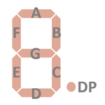 |
Display Fonts:
| Type | Calculator | Number Fonts | Decimal Separator |
Thousands Separator |
Entry Overflow |
Calculating Overflow |
Minus | Memory Indicator |
| µPD276 | Elite Model 3002M |
n.a. |

 Scanning: Display
and keyboard scanning is performed in D0 → D9 direction at a rate of
about 830 Hz. D0 is used for keyboard scanning only:
Scanning: Display
and keyboard scanning is performed in D0 → D9 direction at a rate of
about 830 Hz. D0 is used for keyboard scanning only:
|
• State Time = 1 Clock =
0.025 ms @ CK=40 kHz • Digit Time = 4 States = 0.100 ms @ CK=40 kHz • Scan Time = 12 Digit Times (D1 to D9 with D10 and D11 a dead cycle) = 1.200 ms @ CK=40 kHz |

![]() Device-under-Test:
Device-under-Test:
| • Package Markings Top:
µPD277C H53966 • Package Markings Bottom: • Donor Calculator: MBO de Luxe III, May 1975 |
Keyboard: The MBO de Luxe III makes use of a keyboard assembly with 22 snap action switches and two sliding switches for power and the constant function soldered on a single-sided phenolic PCB. All switches are arranged in a 10*3 matrix with the rows connected to the D0-D9 Outputs (Digit Scan) and the columns connected to the NK (Number Keys), FK1 (Function Keys 1) and FK2 (Function Keys 2) Inputs (Keyboard Scan) of the µPD277 single-chip calculator circuit. The sliding switch of the MBO de Luxe III to enable the constant function is connected between the K Input and the positive power supply VSS.
Keyboard Matrix of the MBO de Luxe III:
µPD277 | ||||
| NK | FK1 | FK2 | K | |
| VSS | [ - K] | |||
| D0 | 2 | = | CE | |
| D1 | 6 | + | ||
| D2 | 4 | − | ||
| D3 | 0 | % | ||
| D4 | 8 | M= | ||
| D5 | 9 | +/− | ||
| D6 | 1 | . | √x | |
| D7 | 5 | × | ||
| D8 | 7 | ÷ | ||
| D9 | 3 | MR/C | ||
![]() Display:
The MBO de Luxe III makes use of an 9-digit NEC LD8122 low-voltage
Vacuum Fluorescent Display (VFD) connected directly to the respective 9 Digit
Outputs D1 to D9 and 8 Segment Outputs SA to SG and SDP of the µPD277 and biased to approximately -31 Volts.
Segment Output SH of the µPD277 to display the Fancy-Four is not used.
Display:
The MBO de Luxe III makes use of an 9-digit NEC LD8122 low-voltage
Vacuum Fluorescent Display (VFD) connected directly to the respective 9 Digit
Outputs D1 to D9 and 8 Segment Outputs SA to SG and SDP of the µPD277 and biased to approximately -31 Volts.
Segment Output SH of the µPD277 to display the Fancy-Four is not used.
Display Layout:
| NEC LD8122 |
|
|
| The Segment drivers A-G and DP (Decimal Point) are connected to the NEC LD8122 display in the pictured way. Segment driver H is not connected to the display. | |
Display Fonts:
| Type | Calculator | Number Fonts | Decimal Separator |
Thousands Separator |
Entry Overflow |
Calculating Overflow |
Minus | Memory Indicator |
| µPD277 | MBO de Luxe III |
n.a. |

 Scanning: Display
and keyboard scanning is performed in D0 → D9 direction at a rate of
about 830 Hz. D0 is used for keyboard scanning only:
Scanning: Display
and keyboard scanning is performed in D0 → D9 direction at a rate of
about 830 Hz. D0 is used for keyboard scanning only:
|
• State Time = 1 Clock =
0.025 ms @ CK=40 kHz • Digit Time = 4 States = 0.100 ms @ CK=40 kHz • Scan Time = 12 Digit Times (D1 to D9 with D10 and D11 a dead cycle) = 1.200 ms @ CK=40 kHz |
If you have additions to the above article please email: joerg@datamath.org.
© Joerg Woerner, March 8, 2025. No reprints without written permission.