DATAMATH CALCULATOR MUSEUM
|
DATAMATH CALCULATOR MUSEUM |
When Rockwell introduced in June 1974 with the A5300 Product Family the first single-chip calculator circuits with LED (Light-Emitting-Diode) Direct-Drive capabilities, it was ahead of competition but not perfect and showed some compromises:
|
• Additional output pins for keyboard scanning • External resistors to limit LED Segment current • External Power-on Reset circuitry • 15 Volts power supply |
Rockwell redesigned the keyboard scanning scheme of the A5300 design and introduced in October 1974 with the A5000 Product Family a new approach omitting the additional output pins. Next step in Rockwell's evolution of single-chip calculator circuits with LED Direct-Drive was the completely redesigned B5000 Product Family, operated from a 9-Volt battery and using an internal voltage doubler instead a 15 Volts power supply. Further improvements were made to the segment drivers, effectively dropping the external current-limiting resistors and even a power-on reset circuitry was integrated on the chip.
 Looking closely into
the B5000 reveals a design very similar to Rockwell's PPS-4/1 (short for Parallel Processing System, 4-bit, Single-chip) system,
a
Digit Processor
competing directly with the Texas Instruments TMS0950
Product Family introduced in March 1975. The programmable ROM (Read-Only
Memory) of the B5000 is with 448 x 8 Bits capacity much smaller than the
TMS0950 ROM with its 1,024 x 8 Bits capacity, while the RAM with 45 x 4 Bits is
almost on par with the TMS0950 sporting 64 x 4 Bits. As a result is the die
size of the B5000 with around 3.4 mm x 3.8 mm significantly smaller than the
TMS0950 which measures about 5.2 mm x 5.3 mm. The CPU architecture of the
PPS-4/1 was designed with electronic calculators in mind and consequently
were the software engineers able to squeeze a fully-featured five-function
calculator with Memory into the small program memory of the B5000.
Looking closely into
the B5000 reveals a design very similar to Rockwell's PPS-4/1 (short for Parallel Processing System, 4-bit, Single-chip) system,
a
Digit Processor
competing directly with the Texas Instruments TMS0950
Product Family introduced in March 1975. The programmable ROM (Read-Only
Memory) of the B5000 is with 448 x 8 Bits capacity much smaller than the
TMS0950 ROM with its 1,024 x 8 Bits capacity, while the RAM with 45 x 4 Bits is
almost on par with the TMS0950 sporting 64 x 4 Bits. As a result is the die
size of the B5000 with around 3.4 mm x 3.8 mm significantly smaller than the
TMS0950 which measures about 5.2 mm x 5.3 mm. The CPU architecture of the
PPS-4/1 was designed with electronic calculators in mind and consequently
were the software engineers able to squeeze a fully-featured five-function
calculator with Memory into the small program memory of the B5000.
The B5000 was developed with a clear focus on low-cost, battery operated handheld calculators using 8-digit LED Displays:
|
• Output drivers for
common-cathode LED displays • Integrated Clock Oscillator • Four Functions and Percent calculations • Floating point operation • Leading zero suppression • Automatic Constant on Multiplication, Division, Addition, and Subtraction • 1- or 2-key Memory with M+, M−, M×, M÷, MR, and CM functionality • 8-digit displays |
Rockwell redesigned shortly after the introduction of the A5300 the keyboard scanning approach and introduced the A5000, A5500 and A5900 products, omitting the additional output drivers for the keyboard rows but still using a -15 Volts power supply. The lifecycle of the A5300 single-chip calculator circuits was rather short, Texas Instruments introduced in March 1975 with their TMS0950 an even more advanced product that could be operated with a single 9V battery and integrated the power-on circuitry, too. At the height of the Calculator War every penny not spent mattered, omitting both an external DC/DC converter and some discrete components from the bill of material made the difference. Rockwell understood the shortcomings of the A5300 and further enhanced the A5000 and A5500 single-chip calculator circuits, leading to the B5000 and B5500.
Early Rockwell LED Direct-Drive Calculator Chips
| Manufacturer | Type Introduction |
VDD | VLED | Constant (M-D-A-S) |
Special Functions |
Program Memory |
Data Memory |
Keyboard Scanning |
Clock Circuitry |
Reset Circuitry |
Segment Current |
Process | Die Size |
| Rockwell | A5300 June 1974 |
-15 V | - 9V | 2-2-2-2 | 6-Function Memory [%] |
504 x 8 bits | 48 x 4 bits | Digit KS Lines |
Internal 1 R |
External 1 R, 1 C 1 Diode |
External 8 R |
8 um PMOS |
4.0 x 3.8 mm2 |
| Rockwell | A5000 Sep. 1974 |
-15 V | - 9V | 2-2-2-2 | 4-Function Memory [%] |
448 x 8 bits | 45 x 4 bits | Digit | Internal 1 R |
External 1 R, 1 C 1 Diode |
External 8 R |
8 um PMOS |
x mm2 |
QUICK-LINK to
Calculator Circuits with LED Direct-Drive.
QUICK-LINK to Rockwell Calculator Integrated Circuits.
| Type | Calculators | Keyboard | Constant (M-D-A-S) |
Digits | Fixed DP | Rounding | Special Functions |
Seg./Dig. Blanking |
(6,7,9) Font |
Entry Overflow |
Calculating Overflow |
| A5300 | APF Mark 26, Rockwell 20R | [+][−][=] | 2-2-2-2 | 8 | Float | None | [M+][M−][M×][M÷][MR][CM] [%] |
LB, TB NONE |
| Description | Comments | |
| Architecture | Single-chip Calculator | Third Generation |
| Category | Digit Processor | Similar to PPS-4 |
| Related | ||
| ROM Size | 3,584 Bits | 448 Words * 8 Bits |
| RAM Size | 192 Bits | 48 Registers * 4 Bits |
| Outputs | 9 Digits 8 Segments 6 Keyboard Scan |
LED Direct Drive / VFD Digit Drivers LED / VFD Segment Drivers Low Current Digit Scan |
| Inputs | 4 Keyboard 1 Direct Input 1 Clear |
Digit to Keyboard Scan-Matrix Keyboard Debounce Override Active High |
Capacity: Up to 8 digits positive and 7 digits negative
Logic: Algebraic Chain Logic with Automatic Constant
[2] [x] [3] [+] [4] [x] [5] [=] → '50.'
Number Entry: Right-justified number entry, entering a ninth digit is ignored
[1] [2] [3] [4] [5] [6] [7] [8] [9] → '12345678.'
Decimal Point: First entered decimal point is used, additional decimal point entries are ignored
[1] [.] [2] [.] [3] → '1.23'
Fixed Decimal Point: Fixed decimal point arithmetic is not supported
Decimal Alignment: Decimal alignment is supported for additions and subtractions
[0] [.] [4] [5] [+] [0] [.] [5] [5] [=] → '1.00'
Clear: Automatic power-up clear implemented. [C] key clears the whole calculator, [CE] key clears last entry of a number
[1] [+] [2] [C] [3] [=] → '3.'; [1] [+] [2] [CE] [3] [=] → '4.'
Change Sign: Not supported. When performing multiplication or division, a negative value can only be assigned to the first number by pressing the [−] key before entering the number
[−] [2] [x] [3] [=] → '-6.'; [−] [2] [x] [−] [3] [=] → '-7.'
Number Display: Right-justified number display with leading-zero suppression
Negative Numbers: Negative numbers are shown with '-' immediate to the left of the number
Calculating Overflow: An overflow shows the result with the all decimal points lit up and is only recoverable using the [C/CE] key. Negative overflow results need to be cleared with pressing the [C/CE] key twice
[1] [2] [3] [4] [5] [x] [1] [2] [3] [4] [5] [=] → '1.5.2.3.9.9.0.2.', [C/CE] → '1.5239902.', [+] [1] [=] → '.5239902.'
[−] [1] [2] [3] [4] [x] [1] [2] [3] [4] [5] [=] → '-.1.5.2.3.3.7.3.', [C/CE] → '-.1523373', [+] → '-.1.5.2.3.3.7.3.'
Memory: 2-key memory with [STO] and [RCL] keys implemented. Memory store is not indicated
[1] [STO], [C/CE] → '0.', [RCL] → '1.'
Divide By Zero: A division of a positive or negative number by zero shows all zeros with all decimal points lit up and is only recoverable using the [C/CE] key
[1] [:] [0] [=] → '0.0.0.0.0.0.0.0.'; [−] [1] [:] [0] [=] → '0.0.0.0.0.0.0.0.'
Timeout: Not supported
Rounding: Rounding of displayed calculating results is not supported
[2] [0] [:] [3] [=] → '6.6666666'
Automatic Constant: Implemented for multiplication (2nd number used as constant), division (2nd), addition (2nd), and subtraction (2nd)
[3] [x] [2] [=] [=] → '12.', [1] [=] → '2.'; [4] [x] [=] [=] → '64.'
[3] [:] [2] [=] [=] → '0.75', [1] [=] → '0.5.'; [4] [:] [=] [=] → '0.25'
[3] [+] [2] [=] [=] → '7.', [1] [=] → '3.'; [4] [+] [=] [=] → '12.'
[3] [−] [2] [=] [=] → '-1.', [1] [=] → '-1.'; [4] [−] [=] [=] → '-4.'
Percent Function: The [+] and [−] keys followed by the [%] key allows mark-up and discount calculations
[2] [0] [+] [5] [%] → '1.', [=] → '21.'
[2] [0] [-] [5] [%] → '1.', [=] → '19.'
Known Calculator Logic Bugs: None
| Item | Min | Typ | Max | Unit | Comments |
| VSS | 0 | V | |||
| VDD | -15.75 | -15.0 | -14.25 | V | |
| VLEDD | -9.0 | 0 | V | LED: -9 Volts, VFD: 0 Volts | |
| IDD | 3.5 | mA | REXT = 56 kOhm | ||
| VOUT | -30 | -30 | 0.3 | V | VFD Output Voltage through 100 kOhm Resistors |
| VIN (KB1..KB4) | VDD | 0.3 | V | Keyboard Matrix to KS1..KS6 | |
| Int. CK | 40 | 80 | 120 | kHz | REXT = 56 kOhm to VDD |
CLOCK GENERATOR
The A5300 single-chip calculator circuit includes an internal oscillator providing the typical PPS-4/1 "A" and "/B" clock terms with a nominal frequency of 80 kHz. The oscillator is designed as a voltage-controlled ring oscillator and is enabled by pulling Pin 3 (VC) with a resistor REXT to VDD. The nominal value of the external resistor - as known from the PPS-4/1 MM76 datasheet and observed on various calculator designs - is 56 kOhm for a typical frequency of 80 kHz. Here at the Datamath Calculator Museum we operate the A5300 DUT with an external 56 kOhm resistor but verify its operation between 30 kOhm and 80 kOhm.
The operating frequency of the internal clock oscillator depends not only on the external resistor, but its supply voltages VDD, too. We observed with our DUT a positive gradient of the oscillation frequency while varying VDD.
POWER ON RESET (PO)
The PO signal of the A5300 is derived from an external resistor, diode and capacitor pulse shaping network which is tied to the power supply pins VSS and VDD. When power comes on, this circuit automatically sets the Program Counter to a fixed starting location and all outputs are set to a "float" state.
DISCRET INPUT (DIN)
The DIN signal of the A5300 is provided for test purposes. When connected to the power supply pin VSS, the keybounce delay time is reduced from more than 10 ms to less than 1 ms.
The Datamath Calculator Museum DCM-50A (PLAYGROUND) supports the Characterization of the A5300 single-chip calculator circuit soldered on a QIP42 Adapter using the DCM-50A Playground DIL42 Adapter mounted on top of the DCM-50A PG Direct Drive Frame Carrier and the voltages VSS set to 9.0V and VDD/VGG set to -6.0V. Alternatively, the more flexible - but less comfortable - DCM-50A Playground BB400 Adapter can be used. Optional recovering of the internal "A" clock term can be accomplished with the DCM-50A Playground PLL Module.
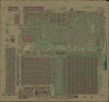
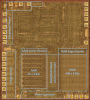
The A5300 was manufactured in a 8 um metal gate PMOS process (metal width = 0.30 mil / 8 um, metal spacing = 0.45 mil / 12 um, diffusion width = 0.30 mil / 8 um, diffusion spacing = 0.30 mil / 8 um).
The die size of the A5300 is approximately 160 mils * 150 mils / 4.0 mm * 3.8 mm.
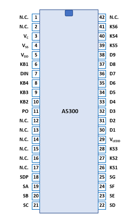
The A5300 uses a standard 0.9” wide 42-pin QIP (Quad In-line Package with a staggered 0.1” / 2.54 mm lead pitch) with plastic body and metal lids.
|
• VSS/VDD - Confirmed Pin Function from Die Photo • (VSS/VDD - Pin Function from Calculator Schematics • N.C. - Confirmed Pin Function from Die Photo or Pin Measurement • (N.C.) - Pin Function from Calculator Schematics |
| Pin | IO | Function | Pin | IO | Function |
| 1 | not connected | 42 | not connected | ||
| 2 | not connected | 41 | O | Keyboard scan 6 | |
| 3 | V | REXT | 40 | O | Keyboard scan 4 |
| 4 | V | Common Voltage VSS | 39 | O | Keyboard scan 5 |
| 5 | V | Negative Voltage VDD | 38 | O | Digit driver 9 (sign) |
| 6 | I | Key-matrix input 1 | 37 | O | Digit driver 8 (MSD) |
| 7 | I | Discrete Input | 36 | O | Digit driver 7 |
| 8 | I | Key-matrix input 4 | 35 | O | Digit driver 6 |
| 9 | I | Key-matrix input 3 | 34 | O | Digit driver 5 |
| 10 | I | Key-matrix input 2 | 33 | O | Digit driver 4 |
| 11 | I | Power On Reset | 32 | O | Digit driver 3 |
| 12 | not connected | 31 | O | Digit driver 2 | |
| 13 | not connected | 30 | O | Digit driver 1 (LSD) | |
| 14 | not connected | 29 | V | Display Voltage VLEDD | |
| 15 | not connected | 28 | O | Keyboard scan 3 | |
| 16 | not connected | 27 | O | Keyboard scan 2 | |
| 17 | not connected | 26 | O | Keyboard scan 1 | |
| 18 | O | Segment driver DP | 25 | O | Segment driver G |
| 19 | O | Segment driver A | 24 | O | Segment driver F |
| 20 | O | Segment driver B | 23 | O | Segment driver E |
| 21 | O | Segment driver C | 22 | O | Segment driver D |
| The Segment drivers A-G and DP (Decimal Point) are connected to the display in the pictured way. | 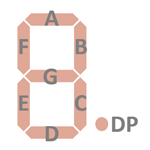 |
The keyboards of all calculators based on the A5300 consist of an x/y-matrix connected to six keyboard scan outputs KS1 to KS6 and the key-matrix inputs KB1 to KB4 (Functions). The keyboard scan outputs are activated together with digit-driver outputs.
Scanning is performed in D9 → D1 direction at a rate of about 370 Hz:
|
• State Time = 1 Clock =
0.0125 ms @ CK=80 kHz • Digit Time = 24 States = 0.30 ms @ CK=80 kHz • Scan Time = 9 Digit Times = 2.70 ms @ CK=80 kHz |
B5000 | ||||
| KB1 | KB2 | KB3 | KB4 | |
| D9 | STO | RCL | % | = |
| D8 | 7 | 8 | 9 | ÷ |
| D7 | 4 | 5 | 6 | × |
| D6 | 1 | 2 | 3 | − |
| D5 | C/CE | 0 | . | + |
| D4 | ||||
| D3 | ||||
| D2 | ||||
| D1 | ||||
Calculators based on the B5000 make use of 9-digit LED (Light-Emitting-Diode) Displays with common cathode architecture.
If you have additions to the above datasheet please email: joerg@datamath.org.
© Joerg Woerner, February 27, 2025. No reprints
without written permission.