DATAMATH CALCULATOR MUSEUM
|
DATAMATH CALCULATOR MUSEUM |
Eiko Business Machine Co., Ltd. introduced its first desktop calculator using LSI (Large Scale Integration) PMOS (p-channel Metal–oxide Semiconductor) technology, the Unitrex 1200, in December 1971. It was designed around the CT5001 single-chip calculator circuit, Cal-Tex's first commercial product. Although the reasons for the rift between Eiko and Cal-Tex remain unclear, Eiko went on to found Frontier Inc. in 1972 in Costa Mesa, California, to design its own calculator chips.
The first product developed by Frontier was the FR1001, a replacement for the CT5001 used in the Unitrex 1200 desktop calculator and its many OEM variants. It was soon followed by the FR1003, which replaced Cal-Tex's CT5005 used in the Unitrex 1200M.
The logic design of the FR1001 is clearly based on Eiko's first electronic desktop calculator, the Unitrex IC8 introduced in November 1968 with an 8-digit display and based on SSI (Small Scale Integration) DTL (Diode-Transistor Logic) Integrated Circuits and a 96-bit Ferrit Core module for its data registers. A distinctive feature of the Unitrex IC8 is how it indicates negative results: Instead of placing a minus sign in front of a number, all digits to the left of the result area are used to display minus signs. For example, a simple calculation like [1] [+] [2 [−] would produce '------1.'. The FR1001, which has a 12-digit display, shows the same result as '-----------1' with the same key sequence.
In another basic test, dividing by zero returns '0.' on both calculators. The Unitrex IC8 also retains an unusual constant function. However, a previous limitation was improved: The IC8's lack of an overflow indicator was fixed to match the CT5001. In both entry and overflow conditions, the display shows '0.0.0.0.0.0.0.0.'.
QUICK-LINK to Frontier Calculator Integrated Circuits.
| Type | Calculators | Keyboard | Constant (M-D-A-S) |
Digits | Fixed DP | Rounding | Special Functions |
Seg./Dig. Blanking |
(6,7,9) Font |
Calculating Overflow |
| FR1001 | Unitrex 1200K | [+=][−=] | 1-2-X-X | 12 | [0...4] | None | None | S1, S8 S1, S8 |
| Description | Comments | |
| Architecture | Single-chip Calculator | First Generation |
| Category | Register Processor | |
| Related | ||
| ROM Size | ||
| RAM Size | ||
| Outputs | 12 Digits 8 Segments |
External VFD Digit Drivers External VFD Segment Drivers |
| Inputs | 3 Keyboard 1 Clear |
Digits to Keyboard Scan-Matrix Active Low |
Capacity: Up to 12 digits positive and 11 digits negative
Logic: Algebraic Adding Machine Logic
[2] [x] [3] [+=] [4] [x] [5] [+=] → '20.'
Number Entry: Right-justified number entry, entering a thirteenth digit is resulting in an overflow condition and is only recoverable using the [C] key
[0|.]: [1] [2] [3] [4] [5] [6] [7] [8] [9] [0] [1] [2] [3] → '0.0.0.0.0.0.0.0.'
Decimal Point: First entered decimal point is used, additional decimal point entries are ignored
[2|.]: [1] [.] [2] [.] [3] → '1.23'
Fixed Decimal Point: The decimal point can be set to [0 1 2 3 4] digits by pressing the [.] key simultaneously with a number key [0] to [4]. Setting the decimal point clears the calculator
[3|.]: [1] [+=] [2] [+=] → '3.000'; [2|.] → '0.00'
Clear: Automatic power-up clear implemented. [C] key clears the whole calculator, [CE] key clears last entry of a number
[0|.]: [1] [+=] [2] [C] [3] [+=] → '3.'; [1] [+=] [2] [CE] [3] [+=] → '4.'
Change Sign: Not supported. When performing multiplication or division, a negative value can only be assigned by pressing the [−=] key after entering the number
[0|.]: [2] [−=] [x] [3] [+=] → '-----------6.'; [2] [−=] [x] [3] [−=] → '6.'
Number Display: Right-justified number display with leading-zero suppression
Negative Numbers: Negative numbers are shown with '-' in all positions left to the leftmost number
Calculating Overflow: An overflow results in displaying zeros with decimal points lit on the eight right positions and is only recoverable using the [C] key
[4|.]: [1] [2] [3] [4] [5] [x] [1] [2] [3] [4] [5] [+=] → '0.0.0.0.0.0.0.0.', [C] → '0.0000'
Divide By Zero: A division of a positive or negative number by zero in displaying a zero
[0|.]: [1] [:] [0] [+=] → '0.', [1] [+=] → '1.'
Rounding: Rounding of displayed calculating results is not supported
[3|.]: [2] [0] [:] [3] [+=] → '6.666'
Constant: Automatic constant can be enabled with an external switch and is implemented for multiplication (1st number used as constant) and division (2nd)
[- K] [0|.]: [3] [x] [2] [+=] [+=] → '6.', [1] [+=] → '7.'; [4] [x] [+=] [+=] → '4.'
[- K] [0|.]: [3] [x] [2] [+=] [+=] → '6.', [1] [+=] → '3.'; [4] [x] [+=] [+=] → '12.'; [C] [4] [x] [+=] [+=] → '4.'
[- K] [2|.]: [3] [:] [2] [+=] [+=] → '1.50', [1] [+=] → '0.50'; [4] [:] [+=] [+=] → '2.00'; [C] [4] [:] [+=] [+=] → '4.'
[- K] [0|.]: [3] [+=] [2] [+=] [+=] → '5.', [1] [+=] → '6.'; [4] [+=] [+=] → '10.'
[- K] [0|.]: [3] [−=] [2] [+=] [+=] → '-----------1.', [1] [+=] → '-----------0.'; [4] [−=] [+=] [+=] → '-----------4.'
Known Calculator Logic Bugs:
Negative Zero Bug : Certain calculations result in displaying a negative zero
[0|.]: [1] [−=] → '-----------1.', [1] [+=] → '-----------0.'
Divide to Negative Zero Bug: Certain calculations result in displaying a negative zero
[4|.]: [0] [.] [0] [0] [0] [1] [−=] → '-------0.0001', [:] [1] [0] [+=] → '-------0.0000'
Fix Point Switch Bug: Changing the position of the Fix Point Switch during number entry leads to unexpected results
[0 2 3 4]: [1] [.] [2] [3] → '1.23', [0 2 3 4]: [+=] → '1230000'
Twelfth Digit Negative Bug: Subtractions with the result larger than eleven digits result temporary in a positive number
[0|.]: [9] [9] [9] [9] [9] [9] [9] [9] [9] [9] [9] [−=] → '-99999999999.', [2] [−=] → '100000000001.', [2] [+=] → '-99999999999.'
Constant Operations Bug: Switching operations in Constant mode is leading to unexpected results
[- K] [0|.: [3] [x] [2] [+=] → '6.', [:] [4] [+=] → '12.'; [CE] [5] [+=] → '15.'; [x] [6] [+=] → '18.'
| Item | Min | Typ | Max | Unit | Comments |
| VSS | 0 | V | |||
| VDD | -17.0 | V | |||
| IDD | tbd | mA | REXT = 100k Ohm, Segment- and | ||
| Ext. CK | 32 | kHz | Two-phase clock | ||
| CP1 Width | 10 | us | Active low | ||
| CP2 Width | 10 | us | Active low | ||
| CP1 to CP2 Delay | 7 | us | Between pulses |
DIGIT DRIVERS
The FR1001 single-chip calculator circuit is manufactured in a PMOS process and its Digit Scanning Outputs are high-side PMOS transistors. For easy interfacing to low-voltage VFDs (Vacuum Fluorescent Displays) or high-voltage gas-discharge displays, an activated digit corresponds to a logical 0 or open output. All other, non-activated digits have the PMOS transistors turned on. We characterized here at the Datamath Calculator Museum the Digit Driver Output pin D2 of an FR1001 and measured an output resistance of around 150 Ohm at an Output Voltage of -1.0 V.
SEGMENT DRIVERS
The FR1001 single-chip calculator circuit is manufactured in a PMOS process and its Segment Outputs are high-side PMOS transistors. For easy interfacing to low-voltage VFDs or high-voltage gas-discharge displays, an activated segment corresponds to a logical 0 or open output. We characterized here at the Datamath Calculator Museum the Segment Driver Output pin SG of an FR1001 and measured an output resistance of 150 Ohm at an Output Voltage of -1.0 V.
The Datamath Calculator Museum DCM-50A (PLAYGROUND) supports the Characterization of the FR1001 single-chip calculator circuit using the DCM-50A Playground DIL42 Adapter mounted on top of the DCM-50A PG Digit Inverter Frame Carrier, the 2-Phase clock and Clear signal generated with the DCM-50A PG 2-Phase Clock Module while the DCM-50A PG KBD123 Keyboard is used for its 12x2 keyboard matrix.
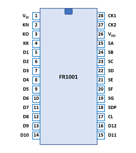
The FR1001 uses a standard 0.6” wide 28-pin DIP (Dual In-line Package with a 0.1” / 2.54 mm lead pitch).
The FR1001 was manufactured in a 7.5 um metal gate PMOS process (metal width = 0.30 mil / 7.5 um, metal spacing = 0.50 mil / 7.5 um, diffusion width = 0.30 mil / 7.5 um, diffusion spacing = 0.30 mil / 7.5 um).
The die size of the FR1001 is approximately 210 mils * 215 mils / 5.3 mm * 5.5 mm.
| Pin | IO | Function | Pin | IO | Function |
| 1 | V | Common Voltage VSS | 28 | I | Clock Input 1 |
| 2 | I | Key-matrix input N | 27 | I | Clock Input 2 |
| 3 | I | Key-matrix input O | 26 | V | Negative Voltage VDD |
| 4 | I | Key-matrix input K | 25 | O | Segment driver A |
| 5 | O | Digit driver 1 (LSD) | 24 | O | Segment driver B |
| 6 | O | Digit driver 2 | 23 | O | Segment driver C |
| 7 | O | Digit driver 3 | 22 | O | Segment driver D |
| 8 | O | Digit driver 4 | 21 | O | Segment driver E |
| 9 | O | Digit driver 5 | 20 | O | Segment driver F |
| 10 | O | Digit driver 6 | 19 | O | Segment driver G |
| 11 | O | Digit driver 7 | 18 | O | Segment driver DP |
| 12 | O | Digit driver 8 | 17 | I | Clear (Active Low) |
| 13 | O | Digit driver 9 | 16 | O | Digit driver 12 (MSD) |
| 14 | O | Digit driver 10 | 15 | O | Digit driver 11 |
| The Segment drivers A-G and DP (Decimal Point) are connected to the display in the pictured way. | 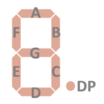 |
The keyboards of all calculators based on the FR1001 consist of an x/y-matrix connected to twelve digit-driver outputs D1-D12 and the key-matrix inputs KN (Numbers), KO (Operations). The [K] switch is connected with two diodes between the digit-driver outputs D2 and D4 and the key-matrix input KK (Constant).
Scanning is performed in D1 → D12 direction at a rate of about 310 Hz:
|
• State Time = 0.5 Clocks = 0.020 ms @ CK=25 kHz • Digit Time = 8 States = 0.160 ms @ CK=25 kHz • Scan Time = 20 Digit Times (D1 to D20 with D13 to D20 a dead cycle) = 3.2 ms @ CK=25 kHz |
FR1001 | |||
| KN | KO | KK | |
| D1 | 2 | . | |
| D2 | 3 | [- K] | |
| D3 | += | ||
| D4 | 6 | [- K] | |
| D5 | |||
| D6 | 9 | −= | |
| D7 | 8 | ||
| D8 | 5 | ||
| D9 | 0 | C | |
| D10 | 1 | CE | |
| D11 | 4 | × | |
| D12 | 7 | ÷ | |
Calculators based on the FR1001 typically make use of 12-digit high-voltage gas-discharge displays.
If you have additions to the above datasheet please email: joerg@datamath.org.
© Joerg Woerner, April 21, 2026. No reprints
without written permission.