DATAMATH CALCULATOR MUSEUM
|
DATAMATH CALCULATOR MUSEUM |
When mid of the 1960s the first Electronic Desktop Calculators appeared on the marked, they used thousands of electronic components soldered on multiple, large printed circuit boards (PCBs). Sharp's CS-10A design as an example used a total of 530 germanium transistors and 2,300 germanium diodes and sold in 1965 for around USD 2,500 or about US$ 25,000 in 2024 money. It is obvious that every component counted, influencing immediately manufacturing costs, product size, reliability and other factors. The first commercially available Integrated Circuit (IC), the SN502 Solid Circuit Flip Flop introduced in March 1960 for US$ 450 per unit, was not an immediate option to reduce manufacturing costs of Electronic Desktop Calculators but paved the way toward compact, reliable and affordable products.
In 1965, Gordon E. Moore - co-founder of Intel - postulated that the number of transistors that can be packed into a given unit of space will double about every two years. This allowed to integrate more and more transistors, diodes and resistors into Integrated Circuits and we differentiate between "Small Scale Integration" (SSI) with complexities in the lower tens of components, "Medium Scale Integration" (MSI) with tens to hundreds of components on a single chip and "Large Scale Integration" (LSI) with one thousand and more components integrated on a small silicon chip. Looking again into Sharp Corporations' Calculator Innovations, we basically can see that around 2,800 discrete components were reduced with the next generation of desktop calculator to around 2,100 discrete components and 28 ICs (SSI) and the following generation used only 72 ICs (SSI and MSI). Next major milestone for Sharp was the introduction of the QT-8D in 1969, reducing the complexity of the design further to 6 ICs (4 LSI and 2 MSI).
In these early days every component mattered and the calculator logic was developed with minimum transistor count defined as highest priority, leading to "hard-wired" algorithm and a bit-serial architecture. Disadvantages of hard-wired logic are not only the difficulty to modify or improve the algorithm but the high engineering efforts, too - no matter if the design is using discrete transistors, SSI, MSI or LSI ICs. The design of LSI ICs was mainly a result of switching from bipolar transistor technology to Metal-Oxide Semiconductor (MOS) technology, allowing higher densities for transistors used with digital functions like logic gates and storage registers found in electronic calculators and computers. In 1969 it was commercially possible to integrate about 1,000 transistors in a p-Channel MOS (PMOS) process on a silicon die measuring about 0.2" x 0.2" (5 mm x 5 mm) and having about 28 to 48 electrical connections to the outside world. Using the equivalent of around 5,000 transistor functions for a typical electronic calculator design, most "Chipsets" for electronic calculators introduced around 1970 consisted of about 3 to 6 LSI ICs. Following Moore's Law, the first "single-chip calculator circuits" were developed around 1971/1972 and it was expected that by 1973 more than 5,000 transistors could be economically integrated on one chip, allowing to shift the focus from lowest possible transistor count to a lower higher flexibility and lower engineering costs. The progress was directly visible in the architecture of single-chip calculator circuits and we differentiate here at the Datamath Calculator Museum between three phases:
|
• Phase 1 - Register Processor with hard-wired Logic and 1-bit or 4-bit Serial Arithmetic Logic Unit (ALU) • Phase 2 - Register Processor with ROM-based Logic and 1-bit or 4-bit Serial Arithmetic Logic Unit (ALU) • Phase 3 - Digit Processors with ROM and RAM (Microcontroller) |
Register Processors are using in most cases shift-register based data memory (SAM, Serial-Access Memory), holding one number of typically 9 to 16 Digits or the equivalent of 36 Bits to 64 Bits in one register. Depending on the ALU, the SAM is organized with either a 1-bit or 4-bit data path. ROM-based logic replaces the hard-wired logic and allows for more flexibility in the algorithm design, e.g. the differences between Adding Machine Logic typically found in desktop calculators and Chain Logic used with portable calculators. Digit Processors on the other hand are using Random-Access Memory (RAM) as data memory and operate one digit (4-bits) a time on numbers, allowing even more flexibility in the algorithm design at the expense of higher transistor count and slower processing time. But Moore's Law did not only predict smaller chips from design iteration to design iteration, but faster chips, too and by 1977 all new single-chip calculator circuit designs used Digit Processors, by then also known as Microcontrollers.
 Looking closely into
the HD36290 reveals a bit-serial Register Processor with ROM-based Logic
instead the hard-wired Logic of its predecessor HD3633. The design uses a
SAM of 3 * 44 Bits (11 Digit Registers) and a very compact ROM with a
capacity of 328 * 17 Bits for the algorithm. The Feature Set of the HD36290 is
almost identical to the HD3633:
Looking closely into
the HD36290 reveals a bit-serial Register Processor with ROM-based Logic
instead the hard-wired Logic of its predecessor HD3633. The design uses a
SAM of 3 * 44 Bits (11 Digit Registers) and a very compact ROM with a
capacity of 328 * 17 Bits for the algorithm. The Feature Set of the HD36290 is
almost identical to the HD3633:
|
• Output drivers for low-voltage VFD up to 35 Volts • Integrated Clock Oscillator • Four Functions and Percent calculations • Floating point operation • Leading zero suppression • Automatic Constant on Multiplication and Division • 9-digit displays |
QUICK-LINK to Hitachi Calculator Integrated Circuits.
| Type | Calculators | Keyboard | Constant (M-D-A-S) |
Digits | Fixed DP | Rounding | Special Functions |
Seg./Dig. Blanking |
(6,7,9) Font |
Entry Overflow |
Calculating Overflow |
| HD36290 | Lloyd's Accumatic 30 | [+][−][=] | 1-2-X-X | 8 | Float | None | [+/−] [%] | NONE S1, S8 |
| Description | Comments | |
| Architecture | Single-chip Calculator | First Generation |
| Category | Register Processor | Bit-serial |
| Related | ||
| ROM Size | 5,576 Bits | 328 Words * 17 Bits |
| RAM Size | 132 Bits | 3 Registers * 44 Bits (11 Digits) |
| Outputs | 10 Digits 8 Segments |
VFD Digit Drivers VFD Segment Drivers |
| Inputs | 2 Keyboard 1 Clear |
Digit to Keyboard Scan-Matrix Active High |
Capacity: Up to 8 digits (positive and negative)
Logic: Algebraic Chain Logic with Automatic Constant
[2] [x] [3] [+] [4] [x] [5] [=] → '50.'
Number Entry: Right-justified number entry, entering a ninth digit is ignored
[1] [2] [3] [4] [5] [6] [7] [8] [9] → '12345678.'
Decimal Point: First entered decimal point is used, additional decimal point entries are ignored
[1] [.] [2] [.] [3] → '1.23'
Fixed Decimal Point: Fixed decimal point arithmetic is not supported
Decimal Alignment: Decimal alignment is not supported
[0] [.] [4] [5] [+] [0] [.] [5] [5] [=] → '1.'
Clear: Automatic power-up clear implemented. [C] key clears the whole calculator, [CE] key clears last entry of a number
[1] [+] [2] [C] [3] [=] → '3.'; [1] [+] [2] [CE] [3] [=] → '4.'
Change Sign: Not supported. When performing multiplication or division, a negative value can only be assigned to the first number by pressing the [−] key before entering the number
[−] [2] [x] [3] [=] → '-6.'; [−] [2] [x] [−] [3] [=] → '-5.'
Number Display: Right-justified number display with leading-zero suppression
Negative Numbers: Negative numbers are shown with '-' in the leftmost position
Calculating Overflow: An overflow shows the result with the decimal point shifted 8 positions to the left and 'C' (or 'E' for negative numbers) in the leftmost position and is only recoverable using the [C] key
[1] [2] [3] [4] [5] [x] [1] [2] [3] [4] [5] [=] → 'C1.5239902'
Divide By Zero: A division of a positive or negative number by zero shows a '0' and 'C' in the leftmost position and is only recoverable using the [C] key
[1] [:] [0] [=] → 'C 0.'; [−] [1] [:] [0] [=] → 'C 0.'
Timeout: Not supported
Rounding: Rounding of displayed calculating results is not supported
[2] [0] [:] [3] [=] → '6.6666666'
Automatic Constant: Implemented for multiplication (1st number used as constant) and division (2nd)
[3] [x] [2] [=] [=] → '18.', [1] [=] → '3.'; [4] [x] [=] → '16.'; [4] [x] [=] [=] → '64.'
[3] [:] [2] [=] [=] → '0.75', [1] [=] → '0.5.'; [4] [:] [=] → '1.'; [4] [:] [=] [=] → '0.25'
[3] [+] [2] [=] [=] → '5.', [1] [=] → '1.'; [4] [+] [=] [=] → '4.'
[3] [−] [2] [=] [=] → '1.', [1] [=] → '1.'; [4] [−] [=] [=] → '4.'
Percent Function: The [%] key following the [x] key allows with the [+] and [−] keys mark-up and discount calculations
[2] [0] [x] [5] [%] → '1.', [=] → '20.'
[2] [0] [x] [5] [%] → '1.', [+] [=] → '21.'
[2] [0] [x] [5] [%] → '1.', [−] [=] → '19.'
Known Calculator Logic Bugs:
Temporary Divide to Negative Zero Bug: Certain calculations result in displaying a negative zero
[1] [−] [2] [=] → '-1.', [:] [1] [0] [0] [0] [0] [=] → '-0.0001', [=] → '-0.', [:] [1] [0] [=] → '0.'
Negative Zero Bug: Certain calculations result in displaying a negative zero
[1] [−] [2] [+] [1] [=] → '-0.'
| Item | Min | Typ | Max | Unit | Comments |
| VSS | 0 | V | |||
| VDD | -7.0 | V | |||
| VGG | -15.0 | V | |||
| IDD | 3.3 | mA | REXT = 100 kOhm, Segment- and | ||
| IGG | 0.7 | mA | Digit-Driver Load 100 kOhm to VDD | ||
| VOUT | -35 | -30 | 0.3 | V | VFD Output Voltage through 100 kOhm Resistors |
| VIN (KN, KF) | -35 | -30 | 0.3 | V | Input Voltage through 100 kOhm Resistors |
| Int. CK | 190 | kHz | REXT = 180 kOhm |
CLOCK GENERATOR
The HD36290 single-chip calculator circuit includes an internal clock oscillator that can be enabled by connecting a resistor between Pin 25 (REXT) and the negative VGG power supply line. Connecting Pin 25 directly to an external clock source overrides the internal clock oscillator and the chip can be operated with frequencies between 50 kHz and about 250 kHz. The external clock frequency should have a duty cycle close to 50% and oscillate between VSS and VDD.
The frequency of the internal clock oscillator is set with the external capacitor REXT, its nominal values is 180 kOhm, respectively for a typical frequency of 180 kHz. Here at the Datamath Calculator Museum we operate the HD36290 Devices-under-Test (DUT) with an external 180 kOhm resistor but verify its operation between 90 kOhm and 270 kOhm.
The operating frequency of the internal clock oscillator depends not only on the external resistor, but its supply voltages VDD and VGG, too. We observed with our DUT a positive gradient of the oscillation frequency for both VDD and VGG variations.
INTER-DIGIT BLANKING
The HD36290 single-chip calculator circuit is blanking its Digit Outputs for one State Time before and after the Segment Output change while scanning the keyboard and display.
The Datamath Calculator Museum DCM-50A (PLAYGROUND) supports the Characterization of the HD36290 single-chip calculator circuit using the DCM-50A Playground DIL42 Adapter mounted on top of the DCM-50A PG Frame Carrier and the voltages VSS set to 7.0V and VDD/VGG set to -8.0V. Alternatively, the more flexible - but less comfortable - DCM-50A Playground BB400 Adapter can be used.
The HD36290 was manufactured in a 7 um metal gate PMOS process (metal width = 0.30 mil / 7 um, metal spacing = 0.30 mil / 7 um, diffusion width = 0.30 mil / 7 um, diffusion spacing = 0.30 mil / 7 um).
The die size of the HD3633 is approximately 190 mils * 175 mils / 4.9 mm * 4.5 mm.
The HD36290 uses a standard 0.6” wide 28-pin DIP (Dual In-line Package with a 0.1” / 2.54 mm lead pitch).
|
• VSS/VDD/VGG - Confirmed Pin Function from Die Photo • (VSS/VDD/VGG) - Pin Function from Calculator Schematics • N.C. - Confirmed Pin Function from Die Photo or Pin Measurement • (N.C.) - Pin Function from Calculator Schematics |
| Pin | IO | Function | Pin | IO | Function |
| 1 | I | Clear input (high) | 28 | V | (VGG) |
| 2 | I | Key-matrix input N | 27 | V | (VSS) |
| 3 | I | Key-matrix input F | 26 | V | (VSS) |
| 4 | O | Digit driver 9 (sign) | 25 | I | CLK/REXT |
| 5 | O | Digit driver 8 | 24 | V | Negative Voltage VDD |
| 6 | o | Digit driver 7 | 23 | V | Negative Voltage VGG |
| 7 | O | Digit driver 6 | 22 | O | Segment driver DP |
| 8 | O | Digit driver 5 | 21 | O | Segment driver A |
| 9 | O | Digit driver 4 | 20 | O | Segment driver B |
| 10 | O | Digit driver 3 | 19 | O | Segment driver C |
| 11 | O | Digit driver 2 | 18 | O | Segment driver D |
| 12 | O | Digit driver 1 (LSD) | 17 | O | Segment driver E |
| 13 | O | Digit driver 0 (n.a.) | 16 | O | Segment driver F |
| 14 | V | Common Voltage VSS | 15 | O | Segment driver G |
| The Segment drivers A-G and DP (Decimal Point) are connected to the display in the pictured way. | 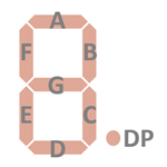 |
The keyboards of all calculators based on the HD36290 consist of an x/y-matrix connected to nine digit-driver outputs and the key-matrix inputs KN (Numbers) and KF (Functions). The [C] key is connected to the dedicated KC input.
Scanning is performed in D0 → D9 direction at a rate of about 1,100 Hz:
|
• State Time = 1 Clocks = 0.01 ms @ CK=100 kHz • Digit Time = 8 States = 0.08 ms @ CK=100 kHz • Scan Time = 11 Digit Times (D0 to D10 with D10 a dead cycle) = 0.88 ms @ CK=100 kHz |
HD36290 | |||
| KN | KF | KC | |
| VSS | C | ||
| D0 | 1 | 0 | |
| D1 | 2 | . | |
| D2 | 3 | + | |
| D3 | 4 | − | |
| D4 | 5 | × | |
| D5 | 6 | ÷ | |
| D6 | 7 | % | |
| D7 | 8 | = | |
| D8 | 9 | CE | |
Calculators based on the HD36290 typically make use of 9-digit low-voltage VFDs (Vacuum Fluorescent Displays).
If you have additions to the above datasheet please email: joerg@datamath.org.
© Joerg Woerner, November 13, 2024. No reprints
without written permission.

