DATAMATH CALCULATOR MUSEUM
|
DATAMATH CALCULATOR MUSEUM |
Hitachi entered the market as supplier of Large Scale Integration (LSI) chips with one thousand and more components integrated on a small silicon chip already in 1971 with the HD3201 chipset for 12-digit or 14-digit electronic desktop calculators. While a typical calculator used - depending of its configuration - 9 or 11 of these "Multi-Chip Slices" manufactured in a p-Channel Metal-Oxide Semiconductor (PMOS) process, could Hitachi reduce the chip count for an 8-digit calculator in 1972 dramatically to two chips, conveniently assembled together in one Ceramic Dual In-line Packages (DIP) with 28-pins. The next step of integration allowed for "true" single-chip calculator circuits like the HD3633 introduced in 1974 and competing directly with Texas Instruments' TMS0850 Product Family.
The HD3633 was developed with a clear focus on battery operated handheld calculators using 8-digit or 9-digit Vacuum Fluorescent Displays (VFDs) and sports a feature set matching perfectly the so-called four-bangers popular in the mid 1970s:
|
• Output drivers for low-voltage VFD up to 35 Volts • Integrated Clock Oscillator • Four Functions and Percent calculations • Floating point operation • Leading zero suppression • Automatic Constant on Multiplication and Division • 8-digit or 9-digit displays |
 Looking closely into
the HD3633 reveals a unique design approach tracing back to the earliest
electronic calculators, its complete logic is realized as a "hard-wired"
Register Processor
instead using the more common approach with a programmable ROM (Read-Only
Memory) to define the calculating algorithm. In 1965, before designers of
electronic desktop calculators could use Integrated Circuits (ICs), a
typical design used around discrete 3,000 transistors and diodes. In 1969 it
was commercially possible to integrate about 1,000 transistors in a
p-Channel MOS (PMOS) process on a silicon die measuring about 0.2" x 0.2" (5
mm x 5 mm) and having about 28 to 48 electrical connections to the outside
world, typical calculators like Sharp's QT-8D split the calculator
electronics into 4 to 6 "Multi-Chip Slices". Gordon E.
Moore - co-founder of Intel - postulated already in the 1960s that the number of
transistors that can be packed into a given unit of space will double about
every two years, paving the way for "single-chip calculator circuits" like
the TMS0100 introduced in September 1971 and
integrating around 5,500 transistors on its silicon die.
Learn more about Hardware Architecture
of Electronic Calculators.
Looking closely into
the HD3633 reveals a unique design approach tracing back to the earliest
electronic calculators, its complete logic is realized as a "hard-wired"
Register Processor
instead using the more common approach with a programmable ROM (Read-Only
Memory) to define the calculating algorithm. In 1965, before designers of
electronic desktop calculators could use Integrated Circuits (ICs), a
typical design used around discrete 3,000 transistors and diodes. In 1969 it
was commercially possible to integrate about 1,000 transistors in a
p-Channel MOS (PMOS) process on a silicon die measuring about 0.2" x 0.2" (5
mm x 5 mm) and having about 28 to 48 electrical connections to the outside
world, typical calculators like Sharp's QT-8D split the calculator
electronics into 4 to 6 "Multi-Chip Slices". Gordon E.
Moore - co-founder of Intel - postulated already in the 1960s that the number of
transistors that can be packed into a given unit of space will double about
every two years, paving the way for "single-chip calculator circuits" like
the TMS0100 introduced in September 1971 and
integrating around 5,500 transistors on its silicon die.
Learn more about Hardware Architecture
of Electronic Calculators.
The lifecycle of the
HD3633 was rather short, Hitachi introduced within a few months improved
products like the HD36290 with reduced manufacturing costs due to smaller packages and
silicon dies and more flexibility and higher functionality due to switching
to programmable ROMs for the calculator logic.
QUICK-LINK to Hitachi Calculator Integrated Circuits.
| Type | Calculators | Keyboard | Constant (M-D-A-S) |
Digits | Fixed DP | Rounding | Special Functions |
Seg./Dig. Blanking |
(6,7,9) Font |
Seg. H" | Entry Overflow |
Calculating Overflow |
| HD3633 | Canon
LD-80 Panther, Lloyd's Accumatic 30 |
[+][−][=] | 1-2-X-X | 8 | Float | None | [+/−] [%] | NONE S1, S8 |
| Description | Comments | |
| Architecture | Single-chip Calculator | First Generation |
| Category | Register Processor | Hard-wired |
| Related | ||
| ROM Size | n.a. | n.a. |
| RAM Size | 136 Bits | 4 Registers * 32 Bits (8 Digits) 8 flags |
| Outputs | 9 Digits 8 Segments 5 Keyboard Scan |
VFD Digit Drivers VFD Segment Drivers Keyboard Matrix |
| Inputs | 4 Keyboard 1 Clear |
Digit to Keyboard Scan-Matrix Active High |
Capacity: Up to 8 digits (positive and negative)
Logic: Algebraic Chain Logic with Automatic Constant
[2] [x] [3] [+] [4] [x] [5] [=] → '50.'
Number Entry: Right-justified number entry, entering a ninth digit is ignored
[1] [2] [3] [4] [5] [6] [7] [8] [9] → '12345678.'
Decimal Point: First entered decimal point is used, additional decimal point entries are ignored
[1] [.] [2] [.] [3] → '1.23'
Fixed Decimal Point: Fixed decimal point arithmetic is not supported
Decimal Alignment: Decimal alignment is not supported
[0] [.] [4] [5] [+] [0] [.] [5] [5] [=] → '1.'
Clear: Automatic power-up clear implemented. [C] key clears the whole calculator, [CE] key clears last entry of a number
[1] [+] [2] [C] [3] [=] → '3.'; [1] [+] [2] [CE] [3] [=] → '4.'
Change Sign: The [+/−] key can be pressed anytime while entering a number
[2] [+/−] [x] [+/−] [3] [=] → '6.'; [1] [+/−] [2] [x] [3] [=] → '36.-'
Number Display: Right-justified number display with leading-zero suppression
Negative Numbers: Negative numbers are shown with '-' immediate to the right of the number
Calculating Overflow: An overflow shows the 8 leading digits of the result and 'C' (or 'E' for negative numbers) in the rightmost position. It is only recoverable using the [C] key
[1] [2] [3] [4] [5] [x] [1] [2] [3] [4] [5] [=] → '15239902C'
Divide By Zero: A division of a positive or negative number by zero shows a '0' and 'C' or 'E', respectively in the rightmost position. It is only recoverable using the [C] key
[1] [:] [0] [=] → '0C'; [−] [1] [:] [0] [=] → '0E'
Timeout: Not supported
Rounding: Rounding of displayed calculating results is not supported
[2] [0] [:] [3] [=] → '6.6666666'
Automatic Constant: Implemented for multiplication (1st number used as constant) and division (2nd)
[3] [x] [2] [=] [=] → '18.', [1] [=] → '3.'; [4] [x] [=] → '16.'; [4] [x] [=] [=] → '64.'
[3] [:] [2] [=] [=] → '0.75', [1] [=] → '0.5.'; [4] [:] [=] → '1.'; [4] [:] [=] [=] → '0.25'
[3] [+] [2] [=] [=] → '5.', [1] [=] → '1.'; [4] [+] [=] [=] → '4.'
[3] [−] [2] [=] [=] → '1.', [1] [=] → '1.'; [4] [−] [=] [=] → '4.'
Percent Function: The [%] key following the [x] key allows with the [+] and [−] keys mark-up and discount calculations
[2] [0] [x] [5] [%] → '1.', [=] → '20.'
[2] [0] [x] [5] [%] → '1.', [+] [=] → '21.'
[2] [0] [x] [5] [%] → '1.', [−] [=] → '19.'
Known Calculator Logic Bugs:
Divide to Negative Zero Bug: Certain calculations result in displaying a negative zero
[1] [−] [2] [=] → '1.-', [:] [1] [0] [0] [0] [0] [=] → '0.0001-', [=] → '0.-'
Negative Zero Bug: Certain calculations result in displaying a negative zero
[1] [−] [2] [+] [1] [=] → '0.-'
| Item | Min | Typ | Max | Unit | Comments |
| VSS | 0 | V | |||
| VDD | -7.0 | V | |||
| VGG | -15.0 | V | |||
| IDD | 3.2 | mA | REXT = 100 kOhm, Segment- and | ||
| IGG | 1.1 | mA | Digit-Driver Load 100 kOhm to VDD | ||
| VOUT | -35 | VPP | 0.3 | V | VFD Output Voltage through 100 kOhm Resistors |
| VIN (K1-K4) | VGG | 0.3 | V | Input Voltage through 100 kOhm Resistors | |
| Int. CK | 90 | kHz | CEXT = 180 pF |
CLOCK GENERATOR
The HD3633 single-chip calculator circuit includes an internal clock oscillator that can be enabled by connecting a capacitor between Pin 20 (CKO) and Pin 21 (CKI). Connecting Pin 21 directly to an external clock source overrides the internal clock oscillator and the chip can be operated with frequencies between 20 kHz and about 100 kHz. The external clock frequency should have a duty cycle close to 50% and oscillate between VSS and VDD.
The frequency of the internal clock oscillator is set with the external capacitor CEXT, its nominal values is 180 pF for a typical frequency of 90 kHz. Here at the Datamath Calculator Museum we operate the HD3633 Devices-under-Test (DUT) with an external 180 pF capacitor but verify its operation between 90 pF and 270 pF.
The operating frequency of the internal clock oscillator depends not only on the external capacitor, but its supply voltages VDD and VGG, too. We observed with our DUT a very stable oscillation frequency over both VDD and VGG variations.
INTER-DIGIT BLANKING
The HD3633 single-chip calculator circuit is blanking its Digit Outputs for one State Time before and after the Segment Output change while scanning the keyboard and display.
The Datamath Calculator Museum DCM-50A (PLAYGROUND) supports the Characterization of the HD3633 single-chip calculator circuit using the DCM-50A Playground DIL42 Adapter mounted on top of the DCM-50A PG Frame Carrier and the voltages VSS set to 7.0V and VDD/VGG set to -8.0V. Alternatively, the more flexible - but less comfortable - DCM-50A Playground BB400 Adapter can be used.
The HD3633 was manufactured in a 7 um metal gate PMOS process (metal width = 0.30 mil / 7 um, metal spacing = 0.30 mil / 7 um, diffusion width = 0.30 mil / 7 um, diffusion spacing = 0.30 mil / 7 um).
The die size of the HD3633 is approximately 195 mils * 185 mils / 5.0 mm * 5.0 mm.
The HD3633 uses a standard 0.6” wide 40-pin DIP (Dual In-line Package with a 0.1” / 2.54 mm lead pitch).
|
• VSS/VDD/VGG - Confirmed Pin Function from Die Photo • (VSS/VDD/VGG) - Pin Function from Calculator Schematics • N.C. - Confirmed Pin Function from Die Photo or Pin Measurement • (N.C.) - Pin Function from Calculator Schematics |
| Pin | IO | Function | Pin | IO | Function |
| 1 | V | Negative Voltage VGG | 40 | O | Digit driver 9 (MSD) |
| 2 | V | Negative Voltage VDD | 39 | O | Digit driver 1 (sign) |
| 3 | O | Keyboard scan 1 | 38 | O | Digit driver 2 (LSD) |
| 4 | O | Keyboard scan 2 | 37 | O | Digit driver 3 |
| 5 | O | Keyboard scan 3 | 36 | O | Digit driver 4 |
| 6 | O | Keyboard scan 4 | 35 | O | Digit driver 5 |
| 7 | O | Keyboard scan 5 | 34 | O | Digit driver 6 |
| 8 | V | Common Voltage VSS | 33 | O | Digit driver 7 |
| 9 | V | Common Voltage VSS | 32 | O | Digit driver 8 |
| 10 | V | Common Voltage VSS | 31 | O | Segment driver DP |
| 11 | I | Key-matrix input 4 | 30 | O | Segment driver H |
| 12 | I | Key-matrix input 3 | 29 | O | Segment driver G |
| 13 | I | Key-matrix input 2 | 28 | O | Segment driver F |
| 14 | I | Key-matrix input 1 | 27 | O | Segment driver E |
| 15 | V | Common Voltage VSS | 26 | O | Segment driver D |
| 16 | I | Clear input (high) | 25 | O | Segment driver C |
| 17 | V | Common Voltage VSS | 24 | O | Segment driver B |
| 18 | V | Common Voltage VSS | 23 | O | Segment driver A |
| 19 | V | Common Voltage VSS | 22 | V | Common Voltage VSS |
| 20 | O | Clock Output (CEXT) | 21 | I | Clock Input (CEXT) |
| The Segment drivers A-G and DP (Decimal Point) are connected to the display in the pictured way. | 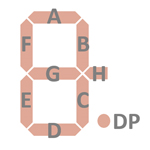 |
The keyboards of all calculators based on the HD3633 consist of an x/y-matrix connected to five keyboard scanning outputs KS1 to KS5 and the key-matrix inputs K1 to K4. The [C] key is connected to the dedicated KC input.
Scanning is performed in D9 → D1 direction at a rate of about 1,100 Hz:
|
• State Time = 1 Clock =
0.0125 ms @ CK=80 kHz • Digit Time = 8 States = 0.1 ms @ CK=80 kHz • Scan Time = 9 Digit Times (D1 to D9) = 0.90 ms @ CK=80 kHz |
Note: The HD3633 single-chip calculator circuit activates only the necessary digit-driver outputs, while displaying a "0." only D2 would be enabled.
HD3633 | |||||
| K1 | K2 | K3 | K4 | KC | |
| VSS | C | ||||
| KS1 | 1 | 2 | × | . | |
| KS2 | 3 | 4 | ÷ | +/− | |
| KS3 | 5 | 6 | + | ||
| KS4 | 7 | 8 | − | % | |
| KS5 | 9 | 0 | = | CE | |
Calculators based on the LH3633 typically make use of 8-digit or 9-digit low-voltage VFDs (Vacuum Fluorescent Displays).
If you have additions to the above datasheet please email: joerg@datamath.org.
© Joerg Woerner, October 12, 2024. No reprints
without written permission.

