DATAMATH CALCULATOR MUSEUM
|
DATAMATH CALCULATOR MUSEUM |
Texas Instruments introduced the TMC0980 Product Family of single-chip calculator circuits in June 1976 with the two scientific calculators SR-40/TI-30 and the counterpart Business Analyst for financial applications. Within two years Texas Instruments introduced with the TI-50, TI-53, and Business Analyst II calculators with a similar feature set in a much smaller housing and powered by two small button style alkaline batteries good for more than 1,000 hours of operation time. This tremendous progress was made possible by replacing the power-hungry LED Display with an LC-Display and switching the manufacturing process of the single-chip calculator circuit from a 9V metal gate PMOS process to a 3V metal gate CMOS process. The TP0320 family is based on the TMC0980 design, an extension of the TMS1000 Microcomputer family, but sports a larger data memory. The TP0320 chip includes 18,432 Bits Read-Only Memory (ROM, 2k*9 Bits) and 832 Bits Random-Access Memory (RAM, 12 Registers * 16 Digits, 64 Bits Display), a 4-bit Arithmetic unit, a programmable PLA for segment decoding and both segment and digit multiplexing for a 9-digit LC-Display with up to 66 segments and 3 common scan lines.
In the midst of the Calculator War end of the Seventies, manufacturing costs of electronic calculators were under extreme pressure and the calculator chip was one of the main cost drivers. The manufacturing costs of an Integrated Circuit (IC) are calculated with:
|
• IC cost = (Die cost + Testing cost + Packaging cost) / Final test yield |
With the die cost roughly proportional to the die area, testing and packaging costs roughly proportional to the pin count, and the final test yield mostly inverse proportional to the die area, goals are well defined: Keep the die size as small as possible while adding new features like timekeeping capabilities or a larger display latch to accommodate LC-Displays with up to 12 digits. With both ROM and RAM size the main contributors to the die area, Texas Instruments decided to reduce the RAM size of twelve 16-digit Registers of the TP0320 to only eight 16-digit Registers and added in lieu of it a 4-bit I/O bus for processor-to-processor communication similar to the failed TP0485 to create Primary-Secondary architectures using two TP0455 chips and effectively doubling ROM and RAM capacity. The first two products based on the TP0455 made perfectly use of the changes from its predecessor TP0320:
|
• TP0455/CD4501: TI-1745 DataCard Time - adding Time, Alarm Time, Stopwatch and a Timer to the TI-1760 DataCard calculator. • TP0455/CD4505 and CD4506: TI-55-II – adding 12-digit LC-Display, statistical functions, conversions and even simple integration to the TI-53 while increasing its program memory from 32 to 56 steps. |
The TP0455 single-chip calculator circuit sports an undisclosed bug and was soon replaced with the TP0456 and most designs were converted with simply adding “50” to the CD (Custom Design) number following the TP0456, while original TP0456 designs started with CD4601:
|
• TP0455/CD4506A: Original TI-55-II
Primary Chip • TP0456/CD4556: Revised TI-55-II Primary Chip • TP0456/CD4614: Original TI-60 Secondary Chip |
The TP0455 chip includes 18,432 Bits Read-Only Memory (ROM, 2k*9 Bits) and 576 Bits Random-Access Memory (RAM, 8 Registers * 16 Digits, 64 Bits Display), a 4-bit Arithmetic unit, a programmable PLA for segment decoding and both segment and digit multiplexing for a 12-digit LC-Display with up to 84 segments and 4 common scan lines. Both chips can work either in a single-chip architecture or in a dual-chip Primary-Secondary architecture.
The TP0455/TP0456 and its later extension TP0458 with an increased ROM and RAM capacity were very successful and many designs made use of their flexibility with both programmable ROM and segment decoder.
| Type | Calculator/Product | Application | Comments |
| TP0455/CD4501C | TI-1745 (DataCard Time) | Basic, Time | Single chip, not released |
| TP0455/CD4505A | TI-55-II | Scientific, 56 steps | Dual chip, Slave - CD4506 |
| TP0455/CD4506A | TI-55-II | Scientific, 56 steps | Dual chip, Primary - CD4505 |
| TP0455/CD4507B | TI-35, TI-40 | Scientific | Single chip, replaces TP0324 |
| TP0455/CD4508C | TI-2000 (Time Manager) | Basic, Time | Single chip |
| TP0455/CD4509B | TI-1890 (Converter) | Basic, Conversion | Single chip |
| TP0455/CD4511A | CA-800 | Cassette Interface | Single chip |
| TP0455/CD4512 | AC-II | not yet discovered | Dual chip, Primary - CD4513 |
| TP0455/CD4513 | AC-II | not yet discovered | Dual chip, Secondary - CD4512 |
| TP0455/CD4514B | TI-2001 GTI, LOGpit | Car, Time | Single chip |
| TP0455/CD4515 | TI-30-II, TI-30 LCD | Scientific | Single chip, replaces TP0320/CD3202 |
| TP0455/CD4518 | CMF | not yet discovered | Single chip |
| TP0455/CD4519 | LCD Programmer | Scientific, Base Conversion | Single chip |
| Description | Comments | |
| Architecture | Single-chip Calculator | Scientific, Financial |
| Category | Digit Processor | 4-bit Digits |
| Related |
TP0320 TP0456 |
9-digit, 7-segment LC-Display Bug fix |
| ROM Size | 18,432 Bits | 2048 Words * 9 Bits |
| RAM Size | 576 Bits | 8 Registers * 16 Digits 64 Bits Display Register |
| Outputs | 4 Common, 21 Segments | Integrated Common Scan Line and Segment Drivers |
| Inputs | 5 Keyboard, CPU-CPU communication | Segment to Keyboard Scan-Matrix |
| Item | Min | Typ | Max | Unit | Comments |
| VDD | 3.0 | V | |||
| VSS | 0 | V | |||
| CK | 250 | 350 | 450 | kHz | Internal oscillator |
The TP0455 was manufactured in a 5 um metal gate CMOS process (metal width = 0.20 mil / 5.0 um, metal spacing = 0.25 mil / 6.0 um, diffusion width = 0.20 mil / 5.0 um, diffusion spacing = 0.20 mil / 5.0 um).
The die size of the TP0455 is approximately 170 mils * 210 mils / 4.3 mm * 5.3 mm.
The TP0455 uses either a 0.4” wide 28-pin SPDIP (Shrink Plastic Dual In-line Package with a 0.07” / 1.778 mm lead pitch)
or a 0.6” wide 40-pin SPDIP (Shrink Plastic Dual In-line Package with a 0.07” / 1.778 mm lead pitch).
TP0455/CD4507 (TI-35)
| Pin | IO | Function | Pin | IO | Function |
| 1 | IO | Key row 5, 3D, 3C, 3A, 3B | 28 | O | LCD COM 1 |
| 2 | I | Key input 2 | 27 | O | LCD COM 2 |
| 3 | IO | Key row 3, 3DP, 2E, 2F, 2G | 26 | I | Key input 1 |
| 4 | IO | Key row 4, 2D, 2C, 2A, 2B | 25 | O | Key row 6, 4DP, 3E, 3F, 3G |
| 5 | I | Key input 3 | 24 | O | Segments SIGN, 8E, 8F, 8G |
| 6 | IO | Key row 1, 2DP, 1E, 1F, 1G | 23 | O | Segments 8D, 8C, 8A, 8BD |
| 7 | I | Key input 4 | 22 | O | Segments 8DP, 7E, 7F, 7G |
| 8 | IO | Key row 1D, 1C, 1A, 1B | 21 | O | Segments 7D, 7C, 7A, 7B |
| 9 | IO | Key row 7, STAT, DEG, GRAD, RAD | 20 | O | Segments 6G, 6F, 6E, 7DP |
| 10 | I | Key input 5 (Wake up) | 19 | O | Segments 6D, 6C, 6A, 6B |
| 11 | V | Negative Voltage VSS | 18 | O | Segments 6DP, 5E, 5F, 5G |
| 12 | VI | Key row 8, Positive Voltage VDD | 17 | O | Segments 5D, 5C, 5A, 5B |
| 13 | O | LCD COM 4 | 16 | O | Segments 5DP, 4E, 4F, 4G |
| 14 | O | LCD COM 3 | 15 | O | Segments 4D, 4C; 4A, 4B |
| Pin | IO | Function | Pin | IO | Function |
| 1 | n.c. | 40 | O | LCD COM 1 | |
| 2 | I | Key input 1 | 39 | O | LCD COM 2 |
| 3 | O | Key row 7, M3DP, M2C, M2F, M2G | 38 | O | Segments |
| 4 | O | Key row 6, M2D, M2E, M2A, M2B | 37 | O | Segments STAT, DEG, GRAD, RAD |
| 5 | I | Key input 2 | 36 | O | Segments MSIGN, M8E, M8F, M8G |
| 6 | O | Key row 4, M2DP, M1C, M1F, M1G | 35 | O | Segments M8D, M8C, M8A, M8B |
| 7 | O | Key row 5, M1D, M1E, M1A, M1G | 34 | O | Segments M8DP, M7E, M7F, M7G |
| 8 | I | Key input 3 | 33 | I | Segments M7D, M7C, M7A, M7B |
| 9 | O | Key row 1, ESIGN, E2E, E2F, E2G | 32 | O | Segments M7DP, M6E, M6F, M6G |
| 10 | O | Key row 2, E2D, E2C, E2A, E2B | 31 | O | Segments M6D, M6C, M6A, M6B |
| 11 | IO | TP0456/CD4555 Pin 7 | 30 | O | Segments M6DP, M5C, M5F, M5G |
| 12 | IO | TP0456/CD4555 Pin 5 | 29 | O | Segments M5D, M5E, M5A, M5B |
| 13 | I | Key input 4 | 28 | O | Segments M5DP, M4C, M4F, M4G |
| 14 | O | Key row 3, PROG, E1E, E1F, E1G | 27 | O | Segments M4D, M4E, M4A, M4B |
| 15 | O | Key row 8, E1D, E1C, E1A, E1B | 26 | TP0456/CD4555 Secondary Pin 16 | |
| 16 | I | Key input 5 (Wake
up) TP0456/CD4555 Secondary Pin 10 |
25 | TP0456/CD4555 Secondary Pin 17 | |
| 17 | V | Negative Voltage VSS | 24 | TP0456/CD4555 Secondary Pin 18 | |
| 18 | V | Positive Voltage VDD | 23 | TP0456/CD4555 Secondary Pin 19 | |
| 19 | O | LCD COM 4 | 22 | O | Segments M4DP, M3C, M3F, M3G |
| 20 | O | LCD COM 3 | 21 | O | Segments M3D, M3E, M3A, M3B |
| The Segment drivers A-G and DP (Decimal Point) are connected to the display in the pictured way. | 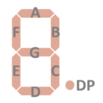 |
The keyboards of all calculators based on the TP0455 Product Family consist of an x/y-matrix connected to up to eight segment outputs with the top row ([ON] key) connected to VDD and the keymatrix inputs K1, K2, K3, K4, and K5. Keyboards with nine rows have the top row ([ON] key) connected only to VDD.
Example for the TI-35 with TP455/CD4507:
| K1 | K2 | K3 | K4 | K5 | |
| VDD | x! | 1/x | % | OFF | ON/C |
| Row 7 | x2 | sin | cos | tan | DRG |
| Row 6 | INV | EE | log | lnx | yX |
| Row 5 | SUM+ | K | ( | ) | ÷ |
| Row 4 | STO | 7 | 8 | 0 | × |
| Row 3 | RCL | 4 | 5 | 6 | − |
| Row 2 | SUM | 1 | 2 | 3 | + |
| Row 1 | EXC | 0 | . | +/− | = |
Example for the TI-55-II with TP455/CD4506:
| K1 | K2 | K3 | K4 | K5 | |
| VDD | 2nd | R/S | √x | OFF | ON/C |
| Row 8 | LRN | RST | SST | BST | Integral |
| Row 7 | hyp | sin | cos | tan | DRG |
| Row 6 | INV | EE | log | lnx | YX |
| Row 5 | SUM+ | x<>y | ( | ) | ÷ |
| Row 4 | STO | 7 | 8 | 0 | × |
| Row 3 | RCL | 4 | 5 | 6 | − |
| Row 2 | EXC | 1 | 2 | 3 | + |
| Row 1 | PI | 0 | . | +/− | = |
Calculators based on the TP0455 make use of 9-digit or 12-digit LCDs (Liquid-Crystal-Displays) with 4 COM (common scan) lines.
If you have additions to the above datasheet please email: joerg@datamath.org.
© Sean Riddle and Joerg Woerner, January 30, 2021. No reprints
without written permission.