DATAMATH CALCULATOR MUSEUM
|
DATAMATH CALCULATOR MUSEUM |
Brother PROCAL 408AY (Version 1)
| Date of introduction: | October 1973 | Display technology: | Fluorescent |
| New price: | Display size: | 8 + Sign | |
| Size: | 6.1" x 4.0" x
1.7" 156 x 101 x 43 mm3 |
||
| Weight: | 8.5 ounces, 241 grams | Serial No: | A4008000 |
| Batteries: | 4*AA | Date of manufacture: | mth 12 year 1973 |
| AC-Adapter: | Model 4086 | Origin of manufacture: | Japan |
| Precision: | 8 | Integrated circuits: | NEC µPD273 |
| Logic: | Chain | Displays: | ISE Electronics DP90A |
| Memories: | |||
| Program steps: | Courtesy of: | Joerg Woerner |

![]()
 Brother
Industries, Ltd. was founded already in 1908 as Yasui Sewing Machine Co, in
Nagoya, Japan and is today mainly known for their printers and sewing machines and
vaguely remembered for their typewriters. Nevertheless entered Brother already
in October 1966 with the fully-transistorized Calther 130 the business of
electronic calculators before switching in October 1969 with the Calther 412 (12
Nixie tubes) and Calther 514 (14 Nixie tubes) to a mix of Integrated Circuits
(ICs) and transistors. Shortly after Texas Instruments
introduced in October 1971 the TMS1802NC
"calculator-on-a-chip", Brother introduced with the PRO-CAL 408 one of the
earliest battery powered, portable electronic calculators.
Brother
Industries, Ltd. was founded already in 1908 as Yasui Sewing Machine Co, in
Nagoya, Japan and is today mainly known for their printers and sewing machines and
vaguely remembered for their typewriters. Nevertheless entered Brother already
in October 1966 with the fully-transistorized Calther 130 the business of
electronic calculators before switching in October 1969 with the Calther 412 (12
Nixie tubes) and Calther 514 (14 Nixie tubes) to a mix of Integrated Circuits
(ICs) and transistors. Shortly after Texas Instruments
introduced in October 1971 the TMS1802NC
"calculator-on-a-chip", Brother introduced with the PRO-CAL 408 one of the
earliest battery powered, portable electronic calculators.
The original PRO-CAL 408 calculator went through different cost-reduction
programs and as of today we identified four different versions:
| Model | Intro. | Keyboard | Display | Calculator Circuit |
Display Driver | Notes |
| PRO-CAL 408 (Version 1) |
12/1971 | Reed-Contacts | 8 * DG8F 1 * DG8F3 |
TMS0105 | 40 discrete Transistors |
3 stacked PCBs Black label |
| PRO-CAL 408 (Version 2) |
09/1972 | Reed-Contacts | 8 * DG8F 1 * DG8F3 |
TMS0105 | 6 Mitsubishi M58212 |
2 stacked PCBs Red label |
| PROCAL 408X | 02/1973 | Rubber-Pad Capacitive |
1 * DP88F | HD3276P, HD3253P | 3 Toshiba TM4352P | Smaller housing 1 PCB |
| PROCAL 408AX | xx/1973 | Rubber-Pad Capacitive |
1 * DP88F | HD3276P, HD3253P | 3 Toshiba TM4352P | Differences to PRO-CAL 408X not known |
A next mayor step was the introduction of this PROCAL 408AY utilizing the first NEC single-chip calculator circuit:
| Model | Intro. | Keyboard | Display | Calculator Circuit |
Display Driver | Notes |
| PROCAL 408AY (Version 1) |
10/1973 | Rubber-Pad Capacitive |
1 * DP90A | µPD273 | None | 1 PCB Label A Series |
| PROCAL 408AY (Version 2) |
12/1973 | Rubber-Pad Conductive |
1 * DP90A | µPD273 | None | 1 PCB Label G Series |
Here at the Datamath Calculator Museum we acquired in 2025 this Brother PROCAL 408AY (Version 1) calculator and its variation PROCAL 408AY (Version 2) on our quest to complete the Characterization of Single-Chip Calculator Circuits manufactured by NEC (Nippon Electric Company) Corporation of Japan.

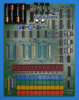
 Dismantling
the featured PROCAL 408AY calculator manufactured in December 1973 in Japan
reveals a cost effective design using on a single-sided printed circuit board
(PCB) for the main electronics and powered by four disposable 1.5 Volts
batteries or a 6-Volt DC power adapter.
Dismantling
the featured PROCAL 408AY calculator manufactured in December 1973 in Japan
reveals a cost effective design using on a single-sided printed circuit board
(PCB) for the main electronics and powered by four disposable 1.5 Volts
batteries or a 6-Volt DC power adapter.
 The Main-PCB is centered around a
µPD273
single-chip calculator circuit manufactured by NEC and the few other remaining
components on the PCB are mainly used to generate the different supply voltages
for the µPD273 and Vacuum Fluorescent Display (VFD) and to bias the anodes and
grids of the display with respect to its filament.
The Main-PCB is centered around a
µPD273
single-chip calculator circuit manufactured by NEC and the few other remaining
components on the PCB are mainly used to generate the different supply voltages
for the µPD273 and Vacuum Fluorescent Display (VFD) and to bias the anodes and
grids of the display with respect to its filament.
 To
better understand the functionality of the rather uncommon µPD273 located so far
only in the PROCAL 408AY, we decided here at the Datamath Calculator Museum to give the featured calculator
a full "Teardown Treatment" and share our findings accordingly.
To
better understand the functionality of the rather uncommon µPD273 located so far
only in the PROCAL 408AY, we decided here at the Datamath Calculator Museum to give the featured calculator
a full "Teardown Treatment" and share our findings accordingly.
![]() Calculating Unit:
The µPD273 located in the featured calculator is considered NEC's first single-chip
calculator circuit with 8-digit display capability and very basic
functionality, following the µPD271 and its low-voltage sibling µPD272. Here
at the Datamath Calculator Museum we don't qualify the µPD271 as a true
single-chip calculator circuit, it is using with the µPD261 an external segment
decoder and driver chip for the calculator display. The µPD273 added both an
internal clock oscillator and segment decoder to the feature set of its
predecessors, rendering it a "true" single-chip calculator circuit. It was
complimented in December 1973 with the µPD277,
a design with 8-digit display capability and integrated 2-key Memory.
Calculating Unit:
The µPD273 located in the featured calculator is considered NEC's first single-chip
calculator circuit with 8-digit display capability and very basic
functionality, following the µPD271 and its low-voltage sibling µPD272. Here
at the Datamath Calculator Museum we don't qualify the µPD271 as a true
single-chip calculator circuit, it is using with the µPD261 an external segment
decoder and driver chip for the calculator display. The µPD273 added both an
internal clock oscillator and segment decoder to the feature set of its
predecessors, rendering it a "true" single-chip calculator circuit. It was
complimented in December 1973 with the µPD277,
a design with 8-digit display capability and integrated 2-key Memory.

 Display:
The featured Brother PROCAL 408AY calculator manufactured
in December 1973 makes use use of a 9-Digit DP90A low-voltage VFD manufactured
by ISE Electronics, inventor of the Vacuum Fluorescent Display
and today better known as NORITAKE ITRON CORPORATION. The DP90A is soldered on s
small PCB which is connected with 19 short wires to the Main-PCB of the
calculator.
Display:
The featured Brother PROCAL 408AY calculator manufactured
in December 1973 makes use use of a 9-Digit DP90A low-voltage VFD manufactured
by ISE Electronics, inventor of the Vacuum Fluorescent Display
and today better known as NORITAKE ITRON CORPORATION. The DP90A is soldered on s
small PCB which is connected with 19 short wires to the Main-PCB of the
calculator.
Display Driver: The term "low-voltage" Vacuum Fluorescent Display might
be misleading when used together with a calculator powered by four 1.5 Volt
batteries. Common VFDs used with portable electronic calculators are usually
operated around 30 Volts, significantly higher than the 10 to 15 Volts operating
voltage of single-chip calculator circuits used in the 1970s. While the first
generation of Texas Instruments TMS0100 single-chip calculator circuits lacked
any display drivers and left the choice of display technology to their
customers, focused the second generation products mainly on Light-Emitting Diode
(LED) technology. In or around 1974, most Western calculator designs still
relied on rather expensive LED technology but Japanese companies like Casio,
Sanyo, Sharp and Toshiba started to leverage the lower manufacturing costs of
VFDs, instead. Texas Instruments introduced in 1974 consequently with the
TMS0850 their first product series focused on battery operated VFD calculators
and modified the integrated segment and digit output drivers to withstand up to
-35 Volts. NEC on the other hand entered the marked of single-chip calculator
circuits in 1973/1974 and focused immediately on compatibility with VFDs. The
µPD273 chips are manufactured in PMOS technology, meaning the
output transistors are "high-side" switching and the most positive voltage of
the chip is labeled VSS for 0 Volt, all other voltages in the
calculator are consequently negative with respect to VSS. Multiplexed
low-voltage VFDs need a voltage difference between its filament and the grids
and anodes of the numbers of around 30 Volts to light up and to avoid "ghosting"
while scanning, the deactivated grids and anodes should be slightly lower than
the filament voltage. An elegant and very common solution is found with this
Brother PROCAL 408AY calculator, too. The grids and anodes of the VFD are "pulled-down"
with 17 resistors (50k Ohm) to around -25 Volts, the filament is biased to
around -23 Volts (Zener Diode) and the µPD273 switches the
relevant grids and anodes to around 0 Volt to lit them up.
Clock: The Brother PROCAL 408AY makes use of the internal clock
oscillator of the µPD273 single-chip calculator circuit with two dedicated pins
and four external components. The primary section of the internal clock
oscillator, Pin 1 (CR1/REXT/CEXT) requires a resistor REXT1 to VGG and a capacitor CEXT1 to VSS.
The secondary secondary section, Pin 28 (SR2/REXT/CEXT)
requires another resistor REXT2 to VGG and another capacitor CEXT2 to VSS.
We identified two resistor/capacitor combinations REXT1/CEXT1 with
nominal values of 150 kOhm and 100 pF, respectively and REXT2/CEXT2
with nominal values of 300 kOhm and 100 pF for a typical frequency of 36
kHz.
Power Supply: The Brother PROCAL 408AY calculator is powered with
four disposable AA-sized 1.5 Volt batteries and uses a
complex DC/DC converter to
generate a total of four voltages:
|
• VDD - Negative supply for
µPD273 (-5.4 V) • VGG - Negative supply for µPD273 (-10.8 V) • VPP - Negative supply for VFD anodes and grids (-24.7 V) • VFIL - AC supply for VFD Filament (2.5 V) |
We measured the operating current of the featured Brother PROCAL 408AY calculator for two different cases:
| Mode | Display | Current VBAT = 6.0 V |
Clock Frequency |
| Calculating | 0. | 50 mA | 35 kHz |
| Calculating | 88888888. | 59 mA | 35 kHz |
Calculating the power consumption at 6 Volts for the Brother PROCAL 408AY results in about 300 mW displaying a '0.' and about 350 mW with all segments but the minus sign illuminated. A very interesting result, a Canon LE-84 calculator with a LED display and using four disposable 1.5 Volt Alkaline batteries and a DC/DC converter for its TMS0801 chip clocks in at around 100 mW displaying a '0.' and 320 mW with all segments lit; showing both an advantage and disadvantage of LED-based calculators versus their VFD-based counterparts:
|
• LED: Only illuminated segments draw current - advantage LED while displaying
'0.' • VFD: Filament uses always current, segment currents are almost negligible - advantage VFD while displaying '88888888.' |

 Keyboard:
The keyboard assembly of the Brother PROCAL 408AY (Version 1) uses 19 plastic keys pushing
small conductive carbon discs mounted in two large silicone rubber membranes
against a thin, self-adhesive plastic foil covering contacts etched on the
Main-PCB. The sliding switch for Power On/Off and the Constant function of the
calculator is wired to the Main-PCB. A closer look at the keyboard
"contacts" shows the two halves separated by a thin PCB trace connected to the common voltage
VSS, one half connected to one of the ten digit-driver outputs of the
µPD273 and the other half connected to a "Mystery" chip converting the voltage
levels to the required level used with the key-matrix inputs NK and FK of the
µPD273. The [C] key is connected directly between common voltage VSS
and the CL input of the µPD273. This unusual style of "capacitive" keyboard
using conductive carbon discs was soon phased out. Enter
PROCAL 408AY (Version 2).
Keyboard:
The keyboard assembly of the Brother PROCAL 408AY (Version 1) uses 19 plastic keys pushing
small conductive carbon discs mounted in two large silicone rubber membranes
against a thin, self-adhesive plastic foil covering contacts etched on the
Main-PCB. The sliding switch for Power On/Off and the Constant function of the
calculator is wired to the Main-PCB. A closer look at the keyboard
"contacts" shows the two halves separated by a thin PCB trace connected to the common voltage
VSS, one half connected to one of the ten digit-driver outputs of the
µPD273 and the other half connected to a "Mystery" chip converting the voltage
levels to the required level used with the key-matrix inputs NK and FK of the
µPD273. The [C] key is connected directly between common voltage VSS
and the CL input of the µPD273. This unusual style of "capacitive" keyboard
using conductive carbon discs was soon phased out. Enter
PROCAL 408AY (Version 2).
 Here
at the Datamath Calculator Museum we use
the DCM-50A Platform to
Characterize and
Reverse-engineer
Single-chip Calculator Circuits. Many designs of electronic calculators do not
use all features of their calculator brains and it would be difficult to unleash
the full potential of the calculator chips in these cases. Additionally are
electronic calculators "closed systems" with limited flexibility to measure
signals, change voltages or clock frequencies, provide additional input keys or
even change the display technology or specifications additional digits. Core
idea of the DCM-50A is providing a generic platform to access all features of a
single-chip calculator circuit and with the
DCM-50A (PLAYGROUND) we
increased the scope from Texas Instruments products to offerings from their
competitors in the 1970s, namely AMI, Cal-Tex, Commodore/MOS Technology,
Electronic Arrays, General Instrument, Hitachi, Litronix, Matsushita,
Mitsubishi, Mostek, National Semiconductor, NEC, Omron, RFT, Rockwell, Sharp,
Toshiba, and Western Digital.
Here
at the Datamath Calculator Museum we use
the DCM-50A Platform to
Characterize and
Reverse-engineer
Single-chip Calculator Circuits. Many designs of electronic calculators do not
use all features of their calculator brains and it would be difficult to unleash
the full potential of the calculator chips in these cases. Additionally are
electronic calculators "closed systems" with limited flexibility to measure
signals, change voltages or clock frequencies, provide additional input keys or
even change the display technology or specifications additional digits. Core
idea of the DCM-50A is providing a generic platform to access all features of a
single-chip calculator circuit and with the
DCM-50A (PLAYGROUND) we
increased the scope from Texas Instruments products to offerings from their
competitors in the 1970s, namely AMI, Cal-Tex, Commodore/MOS Technology,
Electronic Arrays, General Instrument, Hitachi, Litronix, Matsushita,
Mitsubishi, Mostek, National Semiconductor, NEC, Omron, RFT, Rockwell, Sharp,
Toshiba, and Western Digital.
Investigating the Calculator Logic Implementation
of the µPD273 retrieved from the featured Brother PROCAL 408AY reveals some
surprises.
The Constant Function uses a very unusual - and buggy - approach for Multiplication (1st number used as constant), Division (2nd), Addition (1st), and Subtraction (1st) that we refer here in the Datamath Calculator Museum as (M-D-A-S) 1-2-1-1 implementation. The µPD277 dropped Addition and Subtraction from the Constant Function for an (M-D-A-S) 1-2-X-X implementation, while the later µPD276 expanded it again to a more common (M-D-A-S) 1-2-2-2 implementation. The µPD273 was plagued with another bug related to the Percent Function, is displaying after some calculations a negative zero and entering a ninth digit is resulting in an inconvenient overflow condition.
Consequently had the µPD273 a very short lifecycle and was replaced soon with the µPD940, adding more functionality and other improvements to reduce manufacturing costs of battery-operated handheld calculators.
If you have additions to the above article please email: joerg@datamath.org.
© Joerg Woerner, April 18, 2025. No reprints without written permission.