DATAMATH CALCULATOR MUSEUM
|
DATAMATH CALCULATOR MUSEUM |
Heathkit IC-2008
| Date of introduction: | March 15, 1972 | Display technology: | Panaplex II |
| New price: | $139.95 (SRP March 1972) | Display size: | 8 |
| Size: | 10.2" x 6.0" x 3.4" 260 x 153 x 88 mm3 |
||
| Weight: | 46.5 ounces, 1,320 grams | Serial No: | Production batch 01234 |
| Batteries: | Date of manufacture: | mth 03 year 1972 | |
| AC-Adapter: | 120 V or 240 V | Origin of manufacture: | USA |
| Precision: | 8 | Integrated circuits: | TMS1875 |
| Memories: | Displays: | 3*Sperry SP-753 | |
| Program steps: | Courtesy of: | Joerg Woerner |
![]()
 Heath Company of Benton Harbor in Michigan, United States, best known for their high-quality electronic kits branded Heathkit, announced already in March 1972 with the IC-2008 their first
Electronic Desktop calculator. Reasonably priced at $139.95 (around $1,000 in 2023 money), the IC-2008 Desktop calculator competed with fully assembled calculators from Canon, Monroe, Sharp and others. While the specifications of similar priced calculators were almost identical, offered the IC-2008 two unique features: First, a thumb-wheel switch to select the position of the decimal point even at unusual positions like 5 digits behind the decimal point and second, the price-less experience to spend hours and hours assembling your own electronic calculator.
Heath Company of Benton Harbor in Michigan, United States, best known for their high-quality electronic kits branded Heathkit, announced already in March 1972 with the IC-2008 their first
Electronic Desktop calculator. Reasonably priced at $139.95 (around $1,000 in 2023 money), the IC-2008 Desktop calculator competed with fully assembled calculators from Canon, Monroe, Sharp and others. While the specifications of similar priced calculators were almost identical, offered the IC-2008 two unique features: First, a thumb-wheel switch to select the position of the decimal point even at unusual positions like 5 digits behind the decimal point and second, the price-less experience to spend hours and hours assembling your own electronic calculator.
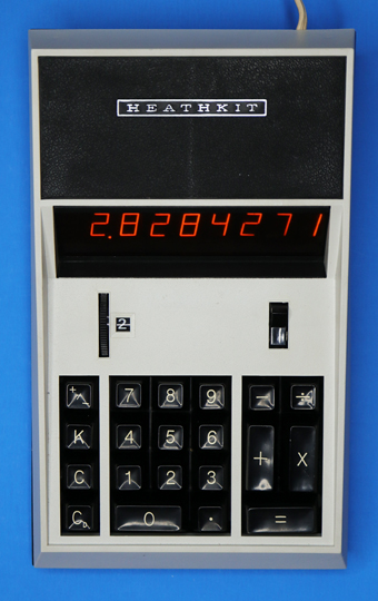
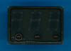
Powering up a Heathkit IC-2008 calculator might take up to one minute before the display is fully functional and instead of the common
'0.' display, the operated is greeted with a glowing, neon-orange 'ooooooo0.' display.
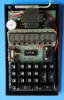
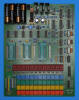
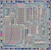
 Dismantling the featured Heathkit IC-2008 sold in
March 1972 to an American hobbyist and assembled in picture-perfect quality, reveals a design centered around a Texas Instruments
TMS1875 single-chip calculator circuit on a conveniently large printed circuit board (PCB) surrounded by the power supply, a keyboard assembled with individual long-stroke push-button switches and many discrete transistors and other components.
Dismantling the featured Heathkit IC-2008 sold in
March 1972 to an American hobbyist and assembled in picture-perfect quality, reveals a design centered around a Texas Instruments
TMS1875 single-chip calculator circuit on a conveniently large printed circuit board (PCB) surrounded by the power supply, a keyboard assembled with individual long-stroke push-button switches and many discrete transistors and other components.
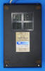
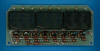 The Main-PCB is connected in typical Heathkit
tradition with individual wires to the power switch, decimal point selection
switch and a secondary PCB with discrete high-voltage drivers and three 3-digit
Sperry SP-753 planar neon gas discharge "Panaplex II" display modules.
The Main-PCB is connected in typical Heathkit
tradition with individual wires to the power switch, decimal point selection
switch and a secondary PCB with discrete high-voltage drivers and three 3-digit
Sperry SP-753 planar neon gas discharge "Panaplex II" display modules.
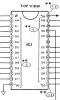
![]() There is a lot of mystery about the TMS1875 chip, suggesting that it is actually a low-cost version of the
TMS1802 with the so-called H-Segment Driver not bonded out to Pin 23 of the 28-pin Dual-Inline package. With the Heathkit IC-2008 sold as kit, the complete schematic
diagram of the calculator is included in its assembly instructions and the TMS1875 is indeed shown without Pin 23 but all other pins are identical with the TMS1802, later renamed to TMS0102, and one of the many members of the
TMS0100 Product Family. Before the marketing-initiated switch of the TMS1802 to TMS0102, Texas Instruments named most Large Scale Integration (LSI) chips manufactured in their PMOS process for electronic calculators in a chronological order, beginning with TMC1730 for the famous Canon
Pocketronic introduced in April 1970 and ending with TMC1876/1877 for the Olivetti Logos 55 desktop printing calculator introduced in 1973 (omitting the TMC1884 bug-fix of the TMC1864 Display Multiplexer of the Compucorp
324G Scientist introduced in December 1971). This gives us a clear timeline for the TMS1875 – centered between the TMC1872 of the
Compucorp 325G Scientist and the TMC1876 - would indicate the readiness for series production early in 1972. And as a matter of fact have all discovered TMS1875 chips Date codes between March 1972 and May 1972, fitting the timeline of the Heathkit IC-2008 introduction. Please notice the leading TMS for
"Texas MOS Standard", while most of the other mentioned chips use a leading TMC for
"Texas MOS Custom", meaning the TMS1875 was not a custom-designed device. While the TMS1802 was renamed shortly after its introduction in September 1971 to TMS0102, missed the TMS1875 the opportunity to be part of the TMS0100, probably due to its disabled leading-zero suppression, a feature specifically mentioned in the TMS0100 documentation.
There is a lot of mystery about the TMS1875 chip, suggesting that it is actually a low-cost version of the
TMS1802 with the so-called H-Segment Driver not bonded out to Pin 23 of the 28-pin Dual-Inline package. With the Heathkit IC-2008 sold as kit, the complete schematic
diagram of the calculator is included in its assembly instructions and the TMS1875 is indeed shown without Pin 23 but all other pins are identical with the TMS1802, later renamed to TMS0102, and one of the many members of the
TMS0100 Product Family. Before the marketing-initiated switch of the TMS1802 to TMS0102, Texas Instruments named most Large Scale Integration (LSI) chips manufactured in their PMOS process for electronic calculators in a chronological order, beginning with TMC1730 for the famous Canon
Pocketronic introduced in April 1970 and ending with TMC1876/1877 for the Olivetti Logos 55 desktop printing calculator introduced in 1973 (omitting the TMC1884 bug-fix of the TMC1864 Display Multiplexer of the Compucorp
324G Scientist introduced in December 1971). This gives us a clear timeline for the TMS1875 – centered between the TMC1872 of the
Compucorp 325G Scientist and the TMC1876 - would indicate the readiness for series production early in 1972. And as a matter of fact have all discovered TMS1875 chips Date codes between March 1972 and May 1972, fitting the timeline of the Heathkit IC-2008 introduction. Please notice the leading TMS for
"Texas MOS Standard", while most of the other mentioned chips use a leading TMC for
"Texas MOS Custom", meaning the TMS1875 was not a custom-designed device. While the TMS1802 was renamed shortly after its introduction in September 1971 to TMS0102, missed the TMS1875 the opportunity to be part of the TMS0100, probably due to its disabled leading-zero suppression, a feature specifically mentioned in the TMS0100 documentation.
![]() Leaves us with the next question – why modifying the leading-zero suppression to output
"half-zeros" instead? Studying the documentation of the SP-753 display module provided by Sperry Information Displays reveals:
"The SP-700 Series was designed mainly for DC applications but can be used in multiplex applications when zeros are not suppressed." and
"The SP-300 Series is recommended for all multiplex applications, including those using MOS/LSI logic." Well, with the
SP-300 Series introduced early in 1972 and immediately replacing the original SP-700 Series, Texas Instruments obviously missed the market window with their TMS1875. And Heathkit probably got a good deal on both the TMS1875 single-chip calculator circuit and the SP-753 display modules.
Leaves us with the next question – why modifying the leading-zero suppression to output
"half-zeros" instead? Studying the documentation of the SP-753 display module provided by Sperry Information Displays reveals:
"The SP-700 Series was designed mainly for DC applications but can be used in multiplex applications when zeros are not suppressed." and
"The SP-300 Series is recommended for all multiplex applications, including those using MOS/LSI logic." Well, with the
SP-300 Series introduced early in 1972 and immediately replacing the original SP-700 Series, Texas Instruments obviously missed the market window with their TMS1875. And Heathkit probably got a good deal on both the TMS1875 single-chip calculator circuit and the SP-753 display modules.
![]() Looking closely at the schematic
diagram of the Heathkit IC-2008 Desktop calculator, you’ll notice a SN7472 flip-flop with its clock input connected to the Digit Driver output D11 of the TMS1875 used for the left-most digit and its two Q and /Q outputs connected to the eight discrete high-voltage drivers. This circuitry changes the pre-programmed scanning order of the TMS1875 from D11→D10→D9…D1 to D11→D10→D8...D2 / D11→D9→D7…D1 (with D10 and D9 actually not used for the display of an 8-digit calculator), an implementation of the
"Interlaced Scan Multiplex Operation" recommended for multiplex operation of SP-700 series displays. The advantage of this approach is that the blanking time normally required within a display envelope to avoid
"ghosting" is accomplished while other display envelopes are addressed. The left-most 3-digit Sperry SP-753 display module of the IC-2008 calculator would see a D11→D8 / D11→D7 scanning order, the middle display module a D6→D4 / D5 scanning order, and the right-most display module a D2 / D3→D1 scanning order, fulfilling the 150 us blanking time requirement of the SP-700 Series.
Looking closely at the schematic
diagram of the Heathkit IC-2008 Desktop calculator, you’ll notice a SN7472 flip-flop with its clock input connected to the Digit Driver output D11 of the TMS1875 used for the left-most digit and its two Q and /Q outputs connected to the eight discrete high-voltage drivers. This circuitry changes the pre-programmed scanning order of the TMS1875 from D11→D10→D9…D1 to D11→D10→D8...D2 / D11→D9→D7…D1 (with D10 and D9 actually not used for the display of an 8-digit calculator), an implementation of the
"Interlaced Scan Multiplex Operation" recommended for multiplex operation of SP-700 series displays. The advantage of this approach is that the blanking time normally required within a display envelope to avoid
"ghosting" is accomplished while other display envelopes are addressed. The left-most 3-digit Sperry SP-753 display module of the IC-2008 calculator would see a D11→D8 / D11→D7 scanning order, the middle display module a D6→D4 / D5 scanning order, and the right-most display module a D2 / D3→D1 scanning order, fulfilling the 150 us blanking time requirement of the SP-700 Series.


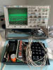
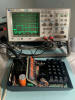 Probing the three Anodes of the center SP-753 display module of the featured calculator and measuring the worst-case blanking time within the display envelope results in about 148 us between D6 and D4, indicating a clock frequency of the TMS1875 above its nominal value of 250 kHz but still within its maximum specification of 400 kHz. The TMS0100 Product Family natively provides a programmable inter-digit blanking time between 0 us and only 24 us at 250 kHz clock frequency, which wouldn’t be sufficient for the SP-300 Series which requires a typical blanking time of 40 us.
 And what about the mysterious H-Segment? We actually connected a Logic Analyzer to the TMS1875 in a fully operational Heathkit IC-2008 Desktop calculator to find the H-Segment static active and decided to go even a step further while preparing our
DCM-50A Platform to allow the
Characterization of Single-Chip Calculator Circuits of the
TMS0100 Product Family.
And what about the mysterious H-Segment? We actually connected a Logic Analyzer to the TMS1875 in a fully operational Heathkit IC-2008 Desktop calculator to find the H-Segment static active and decided to go even a step further while preparing our
DCM-50A Platform to allow the
Characterization of Single-Chip Calculator Circuits of the
TMS0100 Product Family.
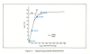 Although the available Logic Analyzer allows to pull Pin 23 with around 100k Ohm
load resistance to either Ground, a negative, or positive voltage, does it not differentiate between an active PMOS transistor, a resistor or even a bond wire to pull the H-Segment active and we varied additionally the load resistor of Pin 23 to measure its output characteristics. Using just 4 different Voltage/Current points, it is already obvious that Pin 23 is driven by an active PMOS transistor with the same strength (geometry) as the other Segment Output pins of a
typical TMS0100 device.
Although the available Logic Analyzer allows to pull Pin 23 with around 100k Ohm
load resistance to either Ground, a negative, or positive voltage, does it not differentiate between an active PMOS transistor, a resistor or even a bond wire to pull the H-Segment active and we varied additionally the load resistor of Pin 23 to measure its output characteristics. Using just 4 different Voltage/Current points, it is already obvious that Pin 23 is driven by an active PMOS transistor with the same strength (geometry) as the other Segment Output pins of a
typical TMS0100 device.
With the TMS1802 being one of the best documented single-chip calculator circuit with its complete technical details specified in various patent applications (see US 6,650,317,B1), we are able to understand the modification of the leading-zero suppression for the TMS1875. Leading-zero suppression and Floating-point operation was introduced during an early phase of electronic calculators to allow for an easier to read display. Instead of outputting for example
'0000.1000' as the result of a calculation, a more readable '0.1' or, depending of the implementation, just
'.1' was displayed for the user. Implementation of leading-zero suppression is rather straightforward:
| • Scanning from left to right till the decimal point position - If the value of the current digit and the previous digit is zero, suppress it |
With the TMS1875 like all members of the TMS0100 Product Family scanning the display from the left-most D11 position towards the right-most D1 position, one would expect that the corresponding digit is simply blanked to suppress it. But with the D11…D1 outputs scanning not only the display but the keyboard matrix, too, Texas Instruments needed to implement leading-zero suppression in a different way and chose to accomplish the desired functionality using the Segment Decoder of the calculator chip.
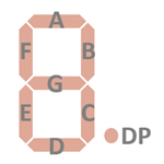 The main purpose of the Segment Decoder of the TMS1875 is converting the numerals, minus sign, overflow and underflow indicators and decimal point into a representation fitting the chosen display technology. Most electronic calculators centered around the TMS0100 single-chip calculator circuits use so-called 7-Segment displays with an extra Dot to the right for the decimal point in different technologies like Light-emitting Diodes (LEDs), Vacuum Fluorescent Displays (VFDs), Liquid Crystal Displays (LCDs), or like this Heathkit IC-2008, planar neon gas discharge displays. Displaying an
'8' would be achieved by illuminating all Segments (A to G), while a '1' would be displayed with just the two segments on the right (B and C) of the 7-Segment pattern. Converting the numerals 0 to 9 in binary-coded decimal (BCD) representation into the corresponding outputs for the seven segments would need obviously a logic module with 4 Inputs for the four bits 23, 22, 21, and 20 of the number and 7 Outputs for the segments A to G. There are different ways to implement complex logic blocks like a 7-Segment Decoder in MOS/LSI circuits with certain advantages and disadvantages. While a
"hard-wired" implementation of the logic on transistor level yields a very compact design, are later modification very difficult to achieve. Using a simple
"Look-up Table" requires just a Read-only Memory (ROM), in this case with 4 Inputs and 7 Outputs or corresponding to 16x7 bits. Obviously very easy to implement and to modify but using a lot of real estate on the silicon chip with each additional Input line doubling the ROM size.
The main purpose of the Segment Decoder of the TMS1875 is converting the numerals, minus sign, overflow and underflow indicators and decimal point into a representation fitting the chosen display technology. Most electronic calculators centered around the TMS0100 single-chip calculator circuits use so-called 7-Segment displays with an extra Dot to the right for the decimal point in different technologies like Light-emitting Diodes (LEDs), Vacuum Fluorescent Displays (VFDs), Liquid Crystal Displays (LCDs), or like this Heathkit IC-2008, planar neon gas discharge displays. Displaying an
'8' would be achieved by illuminating all Segments (A to G), while a '1' would be displayed with just the two segments on the right (B and C) of the 7-Segment pattern. Converting the numerals 0 to 9 in binary-coded decimal (BCD) representation into the corresponding outputs for the seven segments would need obviously a logic module with 4 Inputs for the four bits 23, 22, 21, and 20 of the number and 7 Outputs for the segments A to G. There are different ways to implement complex logic blocks like a 7-Segment Decoder in MOS/LSI circuits with certain advantages and disadvantages. While a
"hard-wired" implementation of the logic on transistor level yields a very compact design, are later modification very difficult to achieve. Using a simple
"Look-up Table" requires just a Read-only Memory (ROM), in this case with 4 Inputs and 7 Outputs or corresponding to 16x7 bits. Obviously very easy to implement and to modify but using a lot of real estate on the silicon chip with each additional Input line doubling the ROM size.
 Texas Instruments chose for the TMS0100 Product Family a more compact but still very flexible approach using a so-called Sum-of-Products (SOP) design, effectively splitting the large
"Look-up Table" ROM into two smaller ROMs and called it in the TMS1802 product announcement
"TI programmable logic array (PLA)" technique. SOP designs are using for the input variables two or more Product (AND) Terms that are summed together for the output values in Sum (OR) Terms. With De Morgan’s theorem that a NAND gate is equivalent to an OR gate with inverted inputs, both the Product and Sum Terms can be converted into NAND gates which can be easily implemented in PMOS technology and a closer look at a TMS0100 silicon chip reveals indeed various PLA structures.
Texas Instruments chose for the TMS0100 Product Family a more compact but still very flexible approach using a so-called Sum-of-Products (SOP) design, effectively splitting the large
"Look-up Table" ROM into two smaller ROMs and called it in the TMS1802 product announcement
"TI programmable logic array (PLA)" technique. SOP designs are using for the input variables two or more Product (AND) Terms that are summed together for the output values in Sum (OR) Terms. With De Morgan’s theorem that a NAND gate is equivalent to an OR gate with inverted inputs, both the Product and Sum Terms can be converted into NAND gates which can be easily implemented in PMOS technology and a closer look at a TMS0100 silicon chip reveals indeed various PLA structures.
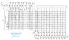 The example of a simple 7-Segment Decoder would result in 10
Product Terms to decode the numbers '0' to '9' out from the BCD input variable and 7 Sum Terms for the segment A to G outputs. The actual 7-Segment Decoder is slightly more complex to decode the various overflow and underflow conditions of the calculation, too
and take care about the minus sign and decimal point. As we can see from the actual design implementation of the TMS1802 circuitry documented in various patent applications, uses the 7-Segment Decoder two different Product Terms for the numeral
zero:
The example of a simple 7-Segment Decoder would result in 10
Product Terms to decode the numbers '0' to '9' out from the BCD input variable and 7 Sum Terms for the segment A to G outputs. The actual 7-Segment Decoder is slightly more complex to decode the various overflow and underflow conditions of the calculation, too
and take care about the minus sign and decimal point. As we can see from the actual design implementation of the TMS1802 circuitry documented in various patent applications, uses the 7-Segment Decoder two different Product Terms for the numeral
zero:
| • 0 for a zero to be displayed and activating the corresponding segment outputs A to F • Q for a zero to be suppressed and not activating any of the segment outputs A to G |
Modifying the leading-zero suppression implemented in the TMS1802 and all other devices from the TMS0100 Product Family to the "half-zeros" of the TMS1875 took a very simple change for the numeral zero:
| • 0 for a zero to be displayed and activating the corresponding segment outputs A to F • Q for a zero to be suppressed but activating the segment outputs C, D, E, and G to output a "half-zero" |
Next step could now be the de-capping of a TMS1875 chip and analyze the corresponding ROM bits of the 7-Segment Decoder PLA but we do not want to harm one of the few surviving IC-2008 calculators.
Designing a product around the TMS1875 chips and SP-753 display modules was at first glance a great idea, but fired almost immediately back on Heath Company. The IC-2008 was an instant success on the market and Heath sold much more of it than it could manufacture, we assume that only around 1,000 to 2,000 of the TMS1875 chip were actually produced by Texas Instruments. Eventually an engineering team redesigned the IC-2008 to accommodate a member of the TMS0100 Product Family without facilitating its implemented leading-zero suppression and the Heathkit IC-2008A was quietly introduced. The chosen TMS0101 is listed in Texas Instruments' selection guide as a so-called "Preferred Type", Heath Company obviously learned their lessons.
If you have additions to the above article please email: joerg@datamath.org.
© Joerg Woerner, February 16, 2002. No reprints without written permission.