DATAMATH CALCULATOR MUSEUM
|
DATAMATH CALCULATOR MUSEUM |
Prinztronic Asset
| Date of introduction: | December 1974 | Display technology: | Fluorescent |
| New price: | Display size: | 8 + Sign | |
| Size: | 5.0" x 3.2" x
1.1" 126 x 81 x 28 mm3 |
||
| Weight: | 4.3 ounces, 123 grams | Serial No: | 34636 |
| Batteries: | 4*AA | Date of manufacture: | mth 01 year 1975 |
| AC-Adapter: | Origin of manufacture: | Taiwan | |
| Precision: | 8 | Integrated circuits: | NEC µPD274 |
| Logic: | Chain | Displays: | Itron DP95A |
| Memories: | |||
| Program steps: | Courtesy of: | Joerg Woerner |

![]() Dixons was founded 1937 by Charles Kalms in Southend, United Kingdom as photographic studio but started soon their own mail order division
and sold in the 1970s a large variety of desktop and handheld calculators under
their Prinztronic brand. This Prinztronic Asset caught our attention when
started to research early single-chip calculator circuits manufactured by NEC
(Nippon Electric Company) Corporation of Japan and we acquired the featured,
non-working calculator in April 2025 from a seller in the United Kingdom.
Dixons was founded 1937 by Charles Kalms in Southend, United Kingdom as photographic studio but started soon their own mail order division
and sold in the 1970s a large variety of desktop and handheld calculators under
their Prinztronic brand. This Prinztronic Asset caught our attention when
started to research early single-chip calculator circuits manufactured by NEC
(Nippon Electric Company) Corporation of Japan and we acquired the featured,
non-working calculator in April 2025 from a seller in the United Kingdom.
To fully understand its design centered around a µPD274 chip, we decided here at the Datamath Calculator Museum to give the featured calculator a full "Teardown Treatment" and share the findings of our 4-step approach accordingly:
|
• Step 1 - Complete
disassembly of the calculator to reverse-engineer its schematic diagram • Step 2 - Bread-boarding the µPD274 to characterize its clock circuitry • Step 3 - Operating the µPD274 in the DCM-50A Platform to characterize its display and keyboard interface • Step 4 - Operating the µPD274 in the DCM-50A Platform to understand its Calculator Logic Implementation |


 Step
1: Dismantling
the featured Asset calculator manufactured in January 1975 by an unknown Original Equipment Manufacturer
(OEM) in Taiwan
reveals a cost effective design using a single-sided printed circuit board
(PCB) for the main electronics and powered by four disposable 1.5 Volts
batteries or a 6-Volt DC power adapter The Main-PCB is centered around a
µPD274
single-chip calculator circuit manufactured by NEC and the few other remaining
components on the PCB are mainly used to generate the different supply voltages
for the µPD274 and Vacuum Fluorescent Display (VFD) and to bias the anodes and
grids of the display with respect to its filament.
Step
1: Dismantling
the featured Asset calculator manufactured in January 1975 by an unknown Original Equipment Manufacturer
(OEM) in Taiwan
reveals a cost effective design using a single-sided printed circuit board
(PCB) for the main electronics and powered by four disposable 1.5 Volts
batteries or a 6-Volt DC power adapter The Main-PCB is centered around a
µPD274
single-chip calculator circuit manufactured by NEC and the few other remaining
components on the PCB are mainly used to generate the different supply voltages
for the µPD274 and Vacuum Fluorescent Display (VFD) and to bias the anodes and
grids of the display with respect to its filament.
![]() The
µPD274 located in the featured calculator is the direct successor of the
µPD273, considered NEC's first single-chip
calculator circuit with 8-digit display capability and very basic functionality.
The short-lived µPD273 was following the original µPD271 and its low-voltage
sibling µPD272. Here at the Datamath Calculator Museum we don't qualify the µPD271
/ µPD272 as a true
single-chip calculator circuits, they are using with the µPD261 an external segment
decoder and driver chip for the calculator display. The µPD273 added both an
internal clock oscillator and segment decoder to the feature set of its
predecessors, rendering it a "true" single-chip calculator circuit. It was
complimented in December 1973 with the µPD277,
a design with 8-digit display capability and integrated 2-key Memory.
The
µPD274 located in the featured calculator is the direct successor of the
µPD273, considered NEC's first single-chip
calculator circuit with 8-digit display capability and very basic functionality.
The short-lived µPD273 was following the original µPD271 and its low-voltage
sibling µPD272. Here at the Datamath Calculator Museum we don't qualify the µPD271
/ µPD272 as a true
single-chip calculator circuits, they are using with the µPD261 an external segment
decoder and driver chip for the calculator display. The µPD273 added both an
internal clock oscillator and segment decoder to the feature set of its
predecessors, rendering it a "true" single-chip calculator circuit. It was
complimented in December 1973 with the µPD277,
a design with 8-digit display capability and integrated 2-key Memory.
![]() The
featured Prinztronic Asset calculator manufactured in January 1975 makes use of
an 9-Digit low-voltage VFD manufactured by Itron and known as Type DP95A,
soldered with its 19 wires directly to the Main-PCB.
The
featured Prinztronic Asset calculator manufactured in January 1975 makes use of
an 9-Digit low-voltage VFD manufactured by Itron and known as Type DP95A,
soldered with its 19 wires directly to the Main-PCB.
 The Prinztronic
Asset makes use of a keyboard assembly with 19 individual spring loaded
long-stroke plastic keys pushing small conductive carbon discs against against
gold plated contacts etched on a single-sided phenolic printed circuit board
(PCB). The sliding switch for Power On/Off is using a small stamped metal part
pressing against two contacts on the PCB while the Constant function of the
calculator is hard-wired on the PCB, using a diode placed on the Main-PCB of the
calculator.
The Prinztronic
Asset makes use of a keyboard assembly with 19 individual spring loaded
long-stroke plastic keys pushing small conductive carbon discs against against
gold plated contacts etched on a single-sided phenolic printed circuit board
(PCB). The sliding switch for Power On/Off is using a small stamped metal part
pressing against two contacts on the PCB while the Constant function of the
calculator is hard-wired on the PCB, using a diode placed on the Main-PCB of the
calculator.
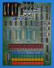
![]() To
understand the functionality of the rather uncommon µPD274 retrieved from the
featured non-working Prinztronic Asset, we decided here at the Datamath
Calculator Museum to give the featured calculator a full "Teardown Treatment". A
first glance at the Main-PCB of the calculator after removing its main components
reveals a marking "MK 800S", a reference to the identical looking Automath
MK-800 calculator.
To
understand the functionality of the rather uncommon µPD274 retrieved from the
featured non-working Prinztronic Asset, we decided here at the Datamath
Calculator Museum to give the featured calculator a full "Teardown Treatment". A
first glance at the Main-PCB of the calculator after removing its main components
reveals a marking "MK 800S", a reference to the identical looking Automath
MK-800 calculator.
![]() A
closer inspection of the Main-PCB and the Keyboard-PCB and their PCB traces gives a few
hints about the µPD274:
A
closer inspection of the Main-PCB and the Keyboard-PCB and their PCB traces gives a few
hints about the µPD274:
|
• The µPD274 uses like the µPD273 two capacitors and resistors for the clock oscillator • The Digit Outputs D1 to D10 are connected to the keyboard and D1 to D8 and D10 to the display • A diode is connecting the Digit Output D8 to the Keyboard Scan Input FK |
Comparing the pinout diagram of the µPD274 with the µPD273 doesn't reveal
any differences - time to dig deeper. Enter Bread-bording.
 Step 2: Based
on the reverse-engineered schematics of the featured Prinztronic Asset and
salvaged µPD274 chip, we bread-boarded the clock oscillator and measured some of
its key parameters. To our surprise
did we measure with the µPD274 a much higher clock frequency than with the
µPD273 in the same setup (VDD = -6.0 V, VGG = -11.0
V, REXT1 = 150 kOhm, REXT2 = 300 kOhm, CEXT1,2
= 100 pF):
Step 2: Based
on the reverse-engineered schematics of the featured Prinztronic Asset and
salvaged µPD274 chip, we bread-boarded the clock oscillator and measured some of
its key parameters. To our surprise
did we measure with the µPD274 a much higher clock frequency than with the
µPD273 in the same setup (VDD = -6.0 V, VGG = -11.0
V, REXT1 = 150 kOhm, REXT2 = 300 kOhm, CEXT1,2
= 100 pF):
| Device-under-Test | Frequency |
| µPD273C K3Y106 | 36.6 kHz |
| µPD274C H4X016 | 50.3 kHz |
 While
measuring the operating frequency of the internal clock oscillator over its
supply voltages VDD and VGG, we noticed a second, major
difference. While both chips have the same nominal operating conditions, does
the µPD274 work with much lower supply voltages than the µPD273:
While
measuring the operating frequency of the internal clock oscillator over its
supply voltages VDD and VGG, we noticed a second, major
difference. While both chips have the same nominal operating conditions, does
the µPD274 work with much lower supply voltages than the µPD273:
| Device-under-Test | Minimum VDD | Minimum VGG |
| µPD273 K3Y106 | -5.0 V | -8.0 V |
| µPD274 H4X016 | -2.0 V | -5.0 V |
We conclude from these observations that the µPD274 is
manufactured in a different PMOS process than the µPD273. Understanding the
requirements to operate the salvaged µPD274 - time to operate it. Enter DCM-50A
Platform.
 Step 3: Here at the Datamath Calculator Museum we use
the DCM-50A Platform to
Characterize and
Reverse-engineer
Single-chip Calculator Circuits. Many designs of electronic calculators do not
use all features of their calculator brains and it would be difficult to unleash
the full potential of the calculator chips in these cases. Additionally are
electronic calculators "closed systems" with limited flexibility to measure
signals, change voltages or clock frequencies, provide additional input keys or
even change the display technology or specifications additional digits. Core
idea of the DCM-50A is providing a generic platform to access all features of a
single-chip calculator circuit and with the
DCM-50A (PLAYGROUND) we
increased the scope from Texas Instruments products to offerings from their
competitors in the 1970s, namely AMI, Cal-Tex, Commodore/MOS Technology,
Electronic Arrays, General Instrument, Hitachi, Litronix, Matsushita,
Mitsubishi, Mostek, National Semiconductor, NEC, Omron, RFT, Rockwell, Sharp,
Toshiba, and Western Digital.
Step 3: Here at the Datamath Calculator Museum we use
the DCM-50A Platform to
Characterize and
Reverse-engineer
Single-chip Calculator Circuits. Many designs of electronic calculators do not
use all features of their calculator brains and it would be difficult to unleash
the full potential of the calculator chips in these cases. Additionally are
electronic calculators "closed systems" with limited flexibility to measure
signals, change voltages or clock frequencies, provide additional input keys or
even change the display technology or specifications additional digits. Core
idea of the DCM-50A is providing a generic platform to access all features of a
single-chip calculator circuit and with the
DCM-50A (PLAYGROUND) we
increased the scope from Texas Instruments products to offerings from their
competitors in the 1970s, namely AMI, Cal-Tex, Commodore/MOS Technology,
Electronic Arrays, General Instrument, Hitachi, Litronix, Matsushita,
Mitsubishi, Mostek, National Semiconductor, NEC, Omron, RFT, Rockwell, Sharp,
Toshiba, and Western Digital.

 Inserting the µPD274 salvaged
from the featured, non-working Prinztronic Asset into the 42-pin ZIF Socket of
the DCM-50A Playground DIL42 Adapter mounted with the
DCM-50A Playground Frame Carrier
on our DCM-50A Platform and wiring all its pins accordingly, resulted in a
working calculator and we could measure its timing of the Display and Keyboard
Scanning Cycle. Again, no differences to the µPD273 and even the Segment Output
SH to display the Fancy-Four is supported with the µPD274.
Inserting the µPD274 salvaged
from the featured, non-working Prinztronic Asset into the 42-pin ZIF Socket of
the DCM-50A Playground DIL42 Adapter mounted with the
DCM-50A Playground Frame Carrier
on our DCM-50A Platform and wiring all its pins accordingly, resulted in a
working calculator and we could measure its timing of the Display and Keyboard
Scanning Cycle. Again, no differences to the µPD273 and even the Segment Output
SH to display the Fancy-Four is supported with the µPD274.
With most of the µPD273 and µPD274 functionality hidden in its
software, we decided to look closer into it. Enter DCM-50A Platform, Part 2.
Step 4: Having with the DCM-50A (PLAYGROUND) a fully
operational calculator with all Keymatrix Positions available, allows looking
deeper into the Calculator Logic Implementation
of the µPD274. In many cases a calculator does not use all the functionality
available with its calculator circuit, the featured Prinztronic Asset as an
example uses 19 keys while the keyboard matrix of the µPD274 would support up to
21 keys and switches (10 Digit Outputs, 2 Keyboard Matrix Inputs and separate
[C] Input). Testing the missing key positions didn't reveal any additional
functionality of the µPD274 compared to the µPD273.
The µPD273 uses for the Constant Function a very unusual - and buggy - approach for Multiplication (1st number used as constant), Division (2nd), Addition (1st), and Subtraction (1st) that we refer here in the Datamath Calculator Museum as (M-D-A-S) 1-2-1-1 implementation. The µPD277 dropped Addition and Subtraction from the Constant Function for an (M-D-A-S) 1-2-X-X implementation, while the later µPD276 expanded it again to a more common (M-D-A-S) 1-2-2-2 implementation. The µPD273 was plagued with another bug related to the Percent Function, is displaying after some calculations a negative zero and entering a ninth digit is resulting in an inconvenient overflow condition.
To our biggest surprise does the µPD274 exhibit exactly the same bugs - meaning its software is identical to the µPD273.
If you have additions to the above article please email: joerg@datamath.org.
© Joerg Woerner, May 3, 2025. No reprints without written permission.