DATAMATH CALCULATOR MUSEUM
|
DATAMATH CALCULATOR MUSEUM |
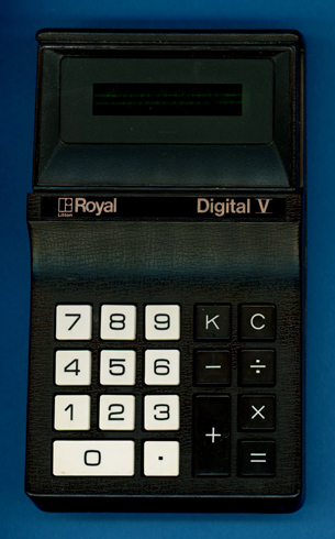
Litton Royal Digital V
| Date of introduction: | April 1972 | Display technology: | Fluorescent |
| New price: | Display size: | 8 | |
| Size: | 5.9" x 3.5" x 1.5" 150 x 90 x 37 mm3 |
||
| Weight: | 11.8 ounces, 335 grams | Serial No: 046684 | 82 06005 |
| Batteries: | 6*AA NiCd | Date of manufacture: | mth 05 year 1972 |
| AC-Adapter: | Origin of manufacture: | Japan | |
| Precision: | 8 | Integrated circuits: | General Instrument 251F, 2*Mitsubishi M58212 |
| Logic: | Chain | Displays: | Futaba 8-CT-01 |
| Memories: | |||
| Program steps: | Courtesy of: | Joerg Woerner | |
| Download manual: | |
![]() Litton Industries,
headquartered in Beverly Hills, California, acquired in 1958
Monroe Calculating Machine Company, an American manufacturer of mechanical calculators.
In 1966 Litton acquired Imperial Typewriter Company Ltd, a very successful manufacturer of typewriters and merged it with its own
Royal Typewriter division. In 1969
the conglomerate was further growing with the acquisition of
Triumph-Adler, the merger of UK Triumph Cycle Company and Adler, a German
manufacturer of bicycles, typewriters, sewing machines and calculators. Early
in the 1970s, Litton sold, depending on the region, electronic calculators under
five different brands: Adler, Imperial, Monroe, Royal and Triumph.
Litton Industries,
headquartered in Beverly Hills, California, acquired in 1958
Monroe Calculating Machine Company, an American manufacturer of mechanical calculators.
In 1966 Litton acquired Imperial Typewriter Company Ltd, a very successful manufacturer of typewriters and merged it with its own
Royal Typewriter division. In 1969
the conglomerate was further growing with the acquisition of
Triumph-Adler, the merger of UK Triumph Cycle Company and Adler, a German
manufacturer of bicycles, typewriters, sewing machines and calculators. Early
in the 1970s, Litton sold, depending on the region, electronic calculators under
five different brands: Adler, Imperial, Monroe, Royal and Triumph.
Litton Industries introduced with the Royal Digital III in November 1971 their first handheld electronic calculator based on General Instrument's 250 single-chip calculator circuits, better known as PICO1. The Digital III was soon complimented with the Digital IV, replacing the unusual 4-digit Vacuum Fluorescent Display (VFD) with a more common 8-digit LED display while maintaining its stylus and gold-plated keyboard contacts to operate the calculator. This Litton Royal Digital V calculator combines a traditional keyboard with an 8-digit VFD while the Litton Monroe 20 calculator combines a traditional keyboard with the 8-digit LED display from the Digital IV. The Digital V calculator was replaced after just 6 months with the RC 80, re-using its electronics in an off-white housing.
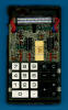
 Dismantling
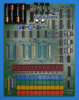
the featured Litton Royal Digital V calculator manufactured in May 1972 in Japan
reveals a compact design based on a double-sided printed circuit board
(PCB) for the main electronics, a single-sided PCB for the power supply and powered
by six internal rechargeable NiCd batteries or an external power adapter.
Dismantling
the featured Litton Royal Digital V calculator manufactured in May 1972 in Japan
reveals a compact design based on a double-sided printed circuit board
(PCB) for the main electronics, a single-sided PCB for the power supply and powered
by six internal rechargeable NiCd batteries or an external power adapter.
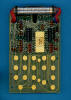 The
Main-PCB is centered around a General Instrument
251F single-chip calculator circuit and the other remaining components on
the PCB are mainly used to interface the display and keyboard. The Power Supply
and Clock Module mounted next to the rechargeable batteries generates the
different supply voltages for the GI 251F and the Vacuum Fluorescent Display
(VFD).
The
Main-PCB is centered around a General Instrument
251F single-chip calculator circuit and the other remaining components on
the PCB are mainly used to interface the display and keyboard. The Power Supply
and Clock Module mounted next to the rechargeable batteries generates the
different supply voltages for the GI 251F and the Vacuum Fluorescent Display
(VFD).
 To
gain some knowledge about the differences between the GI 251F located in this
Litton Royal Digital V and the GI 250 used with this Royal Digital III, we
decided here at the Datamath Calculator Museum to give it a "Teardown
Treatment", sharing our findings accordingly.
To
gain some knowledge about the differences between the GI 251F located in this
Litton Royal Digital V and the GI 250 used with this Royal Digital III, we
decided here at the Datamath Calculator Museum to give it a "Teardown
Treatment", sharing our findings accordingly.
 Calculating Unit:
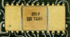
The GI 251F used with the Litton Royal Digital V is the second implementation of
the PICO1 single-chip calculator - on the silicon die labeled as F 1971 76250 PICO11 76251:
Calculating Unit:
The GI 251F used with the Litton Royal Digital V is the second implementation of
the PICO1 single-chip calculator - on the silicon die labeled as F 1971 76250 PICO11 76251:
| • F - Mask Revision
F • 1971 - Copyright of the PICO1 Chip, First silicon June 1971 • 76250 - Internal product designation (Design Root) of General Instrument • PICO11 - Internal product designation of Pico Electronics • 76251 - Internal product designation (Design Variation) of General Instrument |
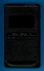
![]() Display:
The featured Litton Royal Digital V calculator manufactured
in May 1972 makes use of an 8-Digit low-voltage VFD manufactured by Futaba and
known as Type 8-CT-01, soldered with its 19 pins directly to the
Main-PCB.
Display:
The featured Litton Royal Digital V calculator manufactured
in May 1972 makes use of an 8-Digit low-voltage VFD manufactured by Futaba and
known as Type 8-CT-01, soldered with its 19 pins directly to the
Main-PCB.
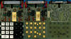
![]() Display Driver: Early "low-voltage" Vacuum Fluorescent Displays are
usually operated between 30 Volts and 45 Volts, significantly higher than the
operating voltage of single-chip calculator circuits. Consequently do most
calculators use some discrete or integrated display drivers on the PCB as
"level-shifters" between the segment and digit outputs of the calculator chip
and the anodes and grids of the VFD. The General Instrument 251F chip uses only
4 digit outputs, labeled D15, D26, D37, and D48, requiring an external "demultiplexer"
to operate an 8-digit display. The dismantled Digital V calculator uses an
interesting and complex approach to interface with the VFD:
Display Driver: Early "low-voltage" Vacuum Fluorescent Displays are
usually operated between 30 Volts and 45 Volts, significantly higher than the
operating voltage of single-chip calculator circuits. Consequently do most
calculators use some discrete or integrated display drivers on the PCB as
"level-shifters" between the segment and digit outputs of the calculator chip
and the anodes and grids of the VFD. The General Instrument 251F chip uses only
4 digit outputs, labeled D15, D26, D37, and D48, requiring an external "demultiplexer"
to operate an 8-digit display. The dismantled Digital V calculator uses an
interesting and complex approach to interface with the VFD:
| • 2 Mitsubishi M58212 chips are providing a combined 12 Inverters • 4 Inverters are used for the D15, D26, D37, and D48 digit outputs • 8 Inverters are used for the A to G and DP segment outputs • 8 discrete, inverting transistors are used for the D1 to D8 VFD grids, with two extra, non-inverting transistors selecting the upper or lower digit groups • 8 discrete, inverting transistors are used for the A to G and DP VFD anodes |
Measuring the supply voltage of the GI 251F chip results in a
value of 24 Volts while the VFD tubes operate with a rather high
voltage of 44 Volts.
Clock: The Power Supply and Clock Module of the Litton Royal Digital V is
providing the clock signal for the GI 251F Chip with a frequency of about 80 to
100 kHz.
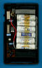
Power Supply: The Litton Royal Digital V calculator is powered with six
internal, AA-sized rechargeable batteries or an external 7.2 Volt power adapter
and uses a complex DC/DC converter to generate a total of four voltages:
|
• VDD - Negative supply for
GI 251F (-24.2 V) • VPP - Negative supply for VFD anodes and grids (-44.0 V) • VBIAS - Negative bias voltage for VFD Filament (-41.0 V) • VFIL - AC supply for VFD Filament (2.5 V) |
We measured the operating current of the featured Litton Royal Digital V calculator for two different cases:
| Mode | Display | Current VBAT = 7.5 V |
Clock Frequency |
| Calculating | 00000000. | 118 mA | 103 kHz |
| Calculating | 88888888. | 120 mA | 103 kHz |
Calculating the power consumption at 7.5 Volts for the Litton Royal Digital V results in about 890 mW displaying a '00000000' and about 900 mW with all segments illuminated.
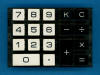 Keyboard:
The keyboard assembly of the Litton Royal Digital V uses 18 spring-supported
plastic keys pushing fingers on a stamped sheet-metal piece against
large, gold-plated contacts on the Main-PCB. The sheet-metal piece itself is
connected through two additional contacts with the Main-PCB.
Keyboard:
The keyboard assembly of the Litton Royal Digital V uses 18 spring-supported
plastic keys pushing fingers on a stamped sheet-metal piece against
large, gold-plated contacts on the Main-PCB. The sheet-metal piece itself is
connected through two additional contacts with the Main-PCB.
 Here
at the Datamath Calculator Museum we use
the DCM-50A Platform to
Characterize and
Reverse-engineer
Single-chip Calculator Circuits. Many designs of electronic calculators do not
use all features of their calculator brains and it would be difficult to unleash
the full potential of the calculator chips in these cases. Additionally are
electronic calculators "closed systems" with limited flexibility to measure
signals, change voltages or clock frequencies, provide additional input keys or
even change the display technology or specifications additional digits. Core
idea of the DCM-50A is providing a generic platform to access all features of a
single-chip calculator circuit and with the
DCM-50A (PLAYGROUND) we
increased the scope from Texas Instruments products to offerings from their
competitors in the 1970s, namely AMI, Cal-Tex, Commodore/MOS Technology,
Electronic Arrays, General Instrument, Hitachi, Litronix, Matsushita,
Mitsubishi, Mostek, National Semiconductor, NEC, Omron, RFT, Rockwell, Sharp,
Toshiba, and Western Digital.
Here
at the Datamath Calculator Museum we use
the DCM-50A Platform to
Characterize and
Reverse-engineer
Single-chip Calculator Circuits. Many designs of electronic calculators do not
use all features of their calculator brains and it would be difficult to unleash
the full potential of the calculator chips in these cases. Additionally are
electronic calculators "closed systems" with limited flexibility to measure
signals, change voltages or clock frequencies, provide additional input keys or
even change the display technology or specifications additional digits. Core
idea of the DCM-50A is providing a generic platform to access all features of a
single-chip calculator circuit and with the
DCM-50A (PLAYGROUND) we
increased the scope from Texas Instruments products to offerings from their
competitors in the 1970s, namely AMI, Cal-Tex, Commodore/MOS Technology,
Electronic Arrays, General Instrument, Hitachi, Litronix, Matsushita,
Mitsubishi, Mostek, National Semiconductor, NEC, Omron, RFT, Rockwell, Sharp,
Toshiba, and Western Digital.
On our quest to document Pico Electronics' PICO1 Chip and its
many descendants like the General Instrument C-500, C-550, CZ-550, C-560, C-570 and
CZL-550, we developed here at the Datamath Calculator Museum three additional
tools for our DCM-50A (PLAYGROUND):
| • DCM-50A
(PLAYGROUND) C-500
Family Adapter: Daughter Board for the
DCM-50A (PLAYGROUND)
Frame Carrier for
General Instrument's C-500 Portfolio • DCM-50A (PLAYGROUND) KBD102 Keyboard: Keyboard with 20 individual keys to support the PICO1-style keyboard reading • DCM-50A (PLAYGROUND) Digilent I/O Extender: Plug-In Board to add six additional Input Signals for the Digilent Discovery |
Comparing the Calculator Logic Implementation of the GI 251F with the Calculator Logic Implementation of the GI 250 chip retrieved from the "Teardown" Litton Royal Digital III reveals no differences other than the missing toggle key.
Don't miss the "Picolator" on the German Richi's Lab site, an Emulator for General Instrument's C-550 single-chip calculator circuit - still using the PICO1 program code from the original GI 250 chip.
If you have additions to the above article please email: joerg@datamath.org.
© Joerg Woerner, July 9, 2025. No reprints without written permission.