DATAMATH CALCULATOR MUSEUM
|
DATAMATH CALCULATOR MUSEUM |
Pico Electronics Ltd. of Glenrothes, Scotland was formed in 1970 by four former General Instrument (GI) engineers to realize their vision of a "single-chip calculator circuit" that they couldn’t pitch successfully to their former managers. It was no other than the CEO of GI providing the Pico Electronics team with startup capital under an extremely smart deal: If the design idea works out as envisioned, Pico Electronics would grant General Instrument the exclusive rights to manufacture and sell the chips on a global base.
The Pico Electronics team was very experienced with developing Chipsets used with electronic calculators, typically using between four and six chips with "hard-coded" logic for the different building blocks. These designs provided almost no flexibility for even minor modifications of the feature set of an electronic calculator and each design used its own set of photomasks for manufacturing. The newly formed Pico Electronics team came up with the idea for a "software-defined" calculator architecture, similar to larger computer systems and using ROM (Read-Only Memory) for its program, shift-register based data memory (SAM, Serial Access Memory), and a small, embedded RISC (Reduced Instruction Set Computer) CPU (Central Processing Unit) for the algorithm. It took the engineers at Pico Electronics only one year between starting their company and sending the first design out to GI for manufacturing and it worked almost perfectly on the first run. While Pico Electronics was fixing some design bugs, General Instrument started in June 1971 quietly some marketing activities for their first single-chip calculator circuit, simply named GI 250 and making its way into the odd Litton Royal Digital III calculator with its unusual 4-digit display and stylus-based keyboard.
Pico Electronics made some interesting design choices with the development of the PICO1 chip, both with the user interface and the embedded calculating logic, but certainly with the implementation of the calculator circuit.
|
• No CE key, pressing a number key after the C key clears the whole calculator while pressing a function key after the C key clears the last entry • Number input is right-to-left, no leading zero suppression. Entering more than 8 digits doesn’t affect the display but the numbers are still registered • Number output is left-to-right, no trailing zero suppression • A missing decimal point is indicating that the numbers are outside of ±1.0 * 10-7 to ±9.9999999 * 107 but still within ±1.0 * 10-20 to ±9.9999999 * 1079 |
|
• Numbers are stored with an eight-digit mantissa and a two-digit exponent, with
'00' to '99' interpreted as 10-20 to 1079 • There is no detection of an exponent roll-over from 1079 to 10-20 or vice versa • The Constant Function operated in two modes, with either one number/different functions or one function/different numbers • A division by Zero is not detected and crashes the algorithm, leading to an endless "counting loop" that can be only interrupted with the C key |
|
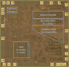
• The PICO1 chip is using a "microcomputer-type" architecture with a CPU, ROM, SAM and glue logic • The CPU is a RISC (Reduced Instruction Set Computer) design with its instruction words between 27 and 63 bits wide • The program in the ROM with its 72 instructions is not sorted by the program flow but the length of the respective instruction words, allowing a more compact, non-rectangular layout of the transistor array • The keyboard interface uses 18 or 19 individual, non-multiplexed keys connected to both dedicated inputs and the display outputs (digits and segments) and read between outputting the numbers • The design of the PICO1 (76250 aka GI 250) uses only four digit outputs for a 4-digit display and an additional toggle key selects between the upper or lower four digits of the 8-digit display register • With the PICO11 (76251 aka GI 251), the upper and lower four digits of the 8-digit display register are automatically toggled, and two additional output signals control an external demultiplexer for an 8-digit display • The PICO1/PICO11 chips lacks a Power-on Clear function for both the registers and program counter, leading to unexpected results if the C key is not pressed before each calculation |
 Sorting
the program of the RISC CPU by the length of its instruction word instead its
program flow resulted physically in a compact layout but added to each
instruction word two so-called "Next Address NA1 and NA2" fields. The Next Address
NA1 field is holding the 7-bit program address if the 'Test' of the
instruction is negative while the NA2 field is holding the 7-bit program
address in case of a positive 'Test' result. Consequently is the layout of the ROM
providing a rectangular area of 72 Words * 14 Bits next to its address
decoder.
Sorting
the program of the RISC CPU by the length of its instruction word instead its
program flow resulted physically in a compact layout but added to each
instruction word two so-called "Next Address NA1 and NA2" fields. The Next Address
NA1 field is holding the 7-bit program address if the 'Test' of the
instruction is negative while the NA2 field is holding the 7-bit program
address in case of a positive 'Test' result. Consequently is the layout of the ROM
providing a rectangular area of 72 Words * 14 Bits next to its address
decoder.
Learn more about the
Logic Implementation of the PICO1 chip, Richard from the German
Richi's Lab
site did an in-depth examination of the silicon die retrieved from a General
Instrument C-550 and even comparing it with the original GI 250 and later GI
GI 251F designs.
Despite its commercial availability about three months before Texas Instruments’ groundbreaking
TMS0100 Product Family, had the original PICO1 chip only modest success and as of today we know with the Litton Royal Digital III and Digital IV calculators only two early design wins. In 1972, the
revised GI 251F made its way into the Litton Royal Digital V and Monroe 20 calculators. After renaming the GI 251F in a marketing campaign to
C-500, the PICO1 started to take off with multiple design wins, most notably the Commodore US 1 and various Iain Jones International, Litton Royal, Sanyo, Unisonic and Universal Data Machine calculators.
The original PICO1 design was used between 1971 and 1974 in four generations of General Instrument single-chip calculator circuits:
|
• 1971: GEN1 GI 250 (76250) and GI 251/251F (76251) – 4-digit display or 4-digit multiplexed 8-digit display, 25 Volt • 1972: GEN1 C-500 (76251) – 4-digit multiplexed 8-digit display, 25 Volt • 1973: GEN2 C-550/CZ-550 - 4-digit multiplexed 8-digit display, trailing zero suppression (CZ-550), 15 Volt • 1973: GEN3 C-560/C-570 - 8-digit display, 15 Volt • 1974: GEN4 CZL-550 – 8-digit display, trailing zero suppression, integrated segment drivers, 15 Volt |
General Instrument launched the C-593 and CF-593 chips in Summer 1973, boldly advertised as "socket-compatible" with Texas Instruments’ TMS0803 and TMS0855, respectively and leading to the very successful C/CF-580, C/CF-590 and C/CF-680 Series of single-chip calculator circuits. General Instrument’s final calculator chip development was the C-680D/C-1680D Series, integrating not only the segment drivers for LED displays, but also the digit drivers and hence allowing "true single-chip calculator designs".
QUICK-LINK to General Instrument Calculator Integrated Circuits.
| Type | Calculators | Keyboard | Constant (M-D-A-S) |
Digits Math |
Digits Display |
Fixed DP | Rounding | Special Functions |
Seg./Dig. Blanking |
(6,7,9) Font |
Entry Overflow |
Calculating Overflow |
| GI 250 | Litton Royal Digital III | [+][−][=] | 2-2-2-2 | 8 | 4 Toggle Key |
Float 10-20-1079 |
None | Constant Number Constant Function |
S1 of 13 S1 of 13 |
|||
| GI 251 | Litton Royal Digital IV | [+][−][=] | 2-2-2-2 | 8 | 4 + 4 Alternating |
Float 10-20-1079 |
None | Constant Number Constant Function |
S1 of 13 S1 of 13 |
|||
| GI 251F | Litton Royal
Digital V Litton Monroe 20 |
[+][−][=] | 2-2-2-2 | 8 | 4 + 4 Alternating |
Float 10-20-1079 |
None | Constant Number Constant Function |
S1 of 13 S1 of 13 |
| Description | Comments | |
| Architecture | Single-chip Calculator | First Generation RISC Architecture |
| Category | Register Processor | |
| Related |
C-500 C-550 |
Rebranded GI 251F Low-voltage Process |
| ROM Size | 3,146 Bits | 72 Words * 27 to 63 Bits |
| RAM Size | 141 Bits | 3 Registers * 44 Bits (11 Digits) 1 Register * 9 Bits |
| Outputs | 4 Digits + 2/3
Control 8 Segments |
VFD Digit Drivers VFD Segment Drivers |
| Inputs | 18/19 Keyboard | Direct Keyboard Inputs |
| Revision | Products | First Prototypes | Comments |
| GI 250 Rev E | Litton Royal Digital III | June 1971 | Mask: E 1971 PICO1 76250 |
| GI 251 Rev E | Litton Royal Digital IV | June 1971 | Mask: E 1971 76250 PICO11 76251 |
| GI 251 Rev F | Litton Royal Digital V Litton Monroe 20 |
Nov. 1971 | Mask: F 1971 76250 PICO11 76251 Renamed in 1972 to C-500 |
Don't miss the "Picolator" on the German Richi's Lab site, an Emulator for General Instrument's C-550 single-chip calculator circuit - still using the PICO1 program code from the original GI 250 chip.
250:
Capacity: Up to 8 digits positive and 7 digits negative with 4-digit display and [↔] key
Logic: Algebraic Chain Logic with Constant
[C] [2] [x] [3] [+] [4] [x] [5] [=] → '50.00', [↔] → '0.0.0.0.'
Number Entry: Right-justified number entry without leading-zero suppression, entering up to 79 digits before the decimal point or 19 digits after the decimal point is registered but in the display ignored
[C] [1] → '0001', [2] [3] [4] [5] [6] [7] [8] [9] [0] → '5678', [↔] → '1234', [:] [1] [0] [0] [0] [=] → '1234', [↔] → '567.8'
[C] [0] [.] → '0000.', [0] [0] [0] [0] [0] [0] [0] [1] [2] [3] → '0.1.2.3.', [↔] → '0.000', [x] → '0.000', [1] [0] [0] [0] → '1000', [=] → '0.000', [↔] → '0.1.2.3.'
Decimal Point: Last entered decimal point is used
[C] [1] [.] [2] [.] [3] → '012.3'
Fixed Decimal Point: Fixed decimal point arithmetic is not supported
Decimal Alignment: Decimal alignment is supported for additions and subtractions
[C] [0] [.] [4] [5] [+] [0] [.] [5] [5] [=] → '1.000'
Clear: No automatic power-up clear implemented. [C] key before entering a number clears the whole calculator, [C] key before entering a function clears last entry of a number
[C] [1] [+] [2] [C] [3] [=] → '3.000'; [C] [1] [+] [2] [C] [+] [3] [=] → '4.000'
Change Sign: Not supported. When performing multiplication or division, a negative value can only be assigned to the first number by pressing the [C] [0] [−] key before entering the number
[C] [0] [−] [2] [x] [3] [=] → '-6.00'; [C] [0] [−] [2] [x] [−] [3] [=] → '-5.00'
Number Display: Left-justified number display without trailing-zero suppression
[C] [1] [.] [2] [3] [x] [1] [0] [0] [=] → '123.0', [↔] → '0.0.0.0.'
[C] [1] [.] [2] [3] [:] [1] [0] [0] [=] → '0.012', [↔] → '3.0.0.0.'
Negative Numbers: Negative numbers are shown with '-' in the leftmost position
Calculating Overflow: An overflow shows the result without the decimal point for numbers up to ±9.9999999 * 1079 with the 8 (for positive and negative numbers) significant digits preserved
[C] [1] [2] [3] [4] [5] [x] [1] [2] [3] [4] [5] [=] → '1523', [↔] → '9902', [:] [1] [0] [0] [0] [=] → '1523, [↔] → '99.02'
[C] [1] [2] [3] [4] [5] [0] [0] [0] [x] [1] [2] [3] [4] [5] [0] [0] [0] [=] → '1523', [↔] → '9902', [:] [1] [0] [0] [0] [=] → '1523', [:] [1] [0] [0] 0] [=] → '1523', [:] [1] [0] [0] [0] [=] → '1523, [↔] → '99.02'
Calculating Underflow: An underflow shows '0.000', [↔] → '0.0.0.0.' for numbers down to ±1.0 * 10-20 with the 8 (for positive and negative numbers) significant digits preserved
[C] [0] [.] [0] [0] [0] [1] [:] [7] [0] [0] [0] [0] [=] → '0.000', [↔] → '0.0.0.0.', [x] [1] [0] [0] [0] [=] → '0.000', [↔] → 0.0.1.4.', [x] [1] [0] [0] [0] [=] → '0.001', [x] [1] [0] [0] [0] [=] → '1.428', [↔] → '5.7.1.4.'
Divide By Zero: A division of a positive or negative number by zero results in an erratic (endless counting) 4 digits (positive) or 4 digits (negative) display with all decimal points lit and is only recoverable using the [C] key
[C] [1] [:] [0] [=] → '?.?.?.?.'; [C] [0] [−] [1] [:] [0] [=] → '?.?.?.?.'
Timeout: Not supported
Rounding: Rounding of displayed calculating results is not supported
[C] [2] [0] [:] [3] [=] → '6.666'
Constant: Constant function can be enabled in two different modes (Constant Number or Constant Function) with a dedicated key for multiplication, division, addition and subtraction
[C] [3] [=] [K] → '3.000', [1] [x] → '3.000', [1] [:] → '0.333', [1] [+] → '4.000', [1] [−] → '-2.00',
[C] [3] [x] [K] → '3.000', [2] [=] → '6.000', [3] [=] → '9.000', [=] → '9.000'
[C] [3] [:] [K] → '3.000', [2] [=] → '0.666', [3] [=] → '1.000', [=] → '0.333'
[C] [3] [+] [K] → '3.000', [2] [=] → '5.000', [3] [=] → '6.000', [=] → '9.000'
[C] [3] [−] [K] → '3.000', [2] [=] → '1.000', [3] [=] → '0.000', [=] → '-3.00'
Reciprocal Function: The reciprocal function is implemented using the [:] key directly followed by the [K] and [=] keys
[C] [4] [:] [K] [=] [=] → '0.250'
Known Calculator Logic Bugs:
Exponent Rollover Bug: Calculations are allowed for numbers between ±1.0 * 10-20 and ±9.9999999 * 1079. Smaller numbers result in an exponents rollover to a large number and vice versa
[C] [0] [.] [0] [0] [0] [0] [0] [0] [1] [x] [K] → '0.000', [↔] → '0.0.0.1.', [1] [.] [2] [3] [=] → '0.000', [↔] → '0.0.0.1.' (1.23 * 10-7), [=] → '0.000' (1.23 * 10-14), [=] → '1230', [↔] → '0000' (1.23 * 10-21 # 1.23 * 1079), eleven times [=] → '123.0', [↔] → '0.0.0.0.' (1.23 * 102)
251F:
Capacity: Up to 8 digits positive and 7 digits negative
Logic: Algebraic Chain Logic with Constant
[C] [2] [x] [3] [+] [4] [x] [5] [=] → '50.000000'
Number Entry: Right-justified number entry without leading-zero suppression, entering up to 79 digits before the decimal point or 19 digits after the decimal point is registered but in the display ignored
[C] [1] → '00000001', [2] [3] [4] [5] [6] [7] [8] [9] [0] → '12345678', [:] [1] [0] [0] [0] [=] → '1234567.8'
[C] [0] [.] → '00000000.', [0] [0] [0] [0] [0] [0] [0] [1] [2] [3] → '0.0000123', [x] → '0.0000000', [1] [0] [0] [0] → '00001000', [=] → '0.0000123'
Decimal Point: Last entered decimal point is used
[C] [1] [.] [2] [.] [3] → '0000012.3'
Fixed Decimal Point: Fixed decimal point arithmetic is not supported
Decimal Alignment: Decimal alignment is supported for additions and subtractions
[C] [0] [.] [4] [5] [+] [0] [.] [5] [5] [=] → '1.0000000'
Clear: No automatic power-up clear implemented. [C] key before entering a number clears the whole calculator, [C] key before entering a function clears last entry of a number
[C] [1] [+] [2] [C] [3] [=] → '3.0000000'; [C] [1] [+] [2] [C] [+] [3] [=] → '4.0000000'
Change Sign: Not supported. When performing multiplication or division, a negative value can only be assigned to the first number by pressing the [C] [0] [−] key before entering the number
[C] [0] [−] [2] [x] [3] [=] → '-6.000000'; [C] [0] [−] [2] [x] [−] [3] [=] → '-5.000000'
Number Display: Left-justified number display without trailing-zero suppression
[C] [1] [.] [2] [3] [x] [1] [0] [0] [=] → '123.00000'
[C] [1] [.] [2] [3] [:] [1] [0] [0] [=] → '0.0123000'
Negative Numbers: Negative numbers are shown with '-' in the leftmost position
Calculating Overflow: An overflow shows the result without the decimal point for numbers up to ±9.9999999 * 1079 with the 8 (for positive and negative numbers) significant digits preserved
[C] [1] [2] [3] [4] [5] [x] [1] [2] [3] [4] [5] [=] → '15239902', [:] [1] [0] [0] [0] [=] → '152399.02'
[C] [1] [2] [3] [4] [5] [0] [0] [0] [x] [1] [2] [3] [4] [5] [0] [0] [0] [=] → '15239902', [:] [1] [0] [0] [0] [=] → '15239902', [:] [1] [0] [0] 0] [=] → '15239902', [:] [1] [0] [0] [0] [=] → '152399.02'
Calculating Underflow: An underflow shows '0.0000000' for numbers down to ±1.0 * 10-20 with the 8 (for positive and negative numbers) significant digits preserved
[C] [0] [.] [0] [0] [0] [1] [:] [7] [0] [0] [0] [0] [=] → '0.0000000', [x] [1] [0] [0] [0] [=] → '0.0000014', [x] [1] [0] [0] [0] [=] → '0.0014285', [x] [1] [0] [0] [0] [=] → '1.4285714'
Divide By Zero: A division of a positive or negative number by zero results in an erratic (endless counting) 8 digits (positive) or 7 digits (negative) display with all decimal points lit and is only recoverable using the [C] key
[C] [1] [:] [0] [=] → '?.?.?.?.?.?.?.?.'; [C] [0] [−] [1] [:] [0] [=] → '.?.?.?.?.?.?.?.'
Timeout: Not supported
Rounding: Rounding of displayed calculating results is not supported
[C] [2] [0] [:] [3] [=] → '6.6666666'
Constant: Constant function can be enabled in two different modes (Constant Number or Constant Function) with a dedicated key for multiplication, division, addition and subtraction
[C] [3] [=] [K] → '3.0000000', [1] [x] → '3.0000000', [1] [:] → '0.3333333', [1] [+] → '4.0000000', [1] [−] → '-2.000000',
[C] [3] [x] [K] → '3.0000000', [2] [=] → '6.0000000', [3] [=] → '9.0000000', [=] → '9.0000000'
[C] [3] [:] [K] → '3.0000000', [2] [=] → '0.6666666', [3] [=] → '1.0000000', [=] → '0.3333333'
[C] [3] [+] [K] → '3.0000000', [2] [=] → '5.0000000', [3] [=] → '6.0000000', [=] → '9.0000000'
[C] [3] [−] [K] → '3.0000000', [2] [=] → '1.0000000', [3] [=] → '0.0000000', [=] → '-3.000000'
Reciprocal Function: The reciprocal function is implemented using the [:] key directly followed by the [K] and [=] keys
[C] [4] [:] [K] [=] [=] → '0.2500000'
Known Calculator Logic Bugs:
Exponent Rollover Bug: Calculations are allowed for numbers between ±1.0 * 10-20 and ±9.9999999 * 1079. Smaller numbers result in an exponents rollover to a large number and vice versa
[C] [0] [.] [0] [0] [0] [0] [0] [0] [1] [x] [K] → '0.0000001', [1] [.] [2] [3] [=] → '0.0000001' (1.23 * 10-7), [=] → '0.0000000' (1.23 * 10-14), [=] → '12300000' (1.23 * 10-21 # 1.23 * 1079), eleven times [=] → '123.00000' (1.23 * 102)
| Item | Min | Typ | Max | Unit | Comments |
| VSS | 0 | V | |||
| VDD | -25.0 | V | |||
| IDD | 12.0 | mA | REXT = 100k Ohm,
Segment- and Digit-Driver Load 100k Ohm to VDD |
||
| VOUT | -30 | -25 | 0.3 | V | VFD Output Voltage through 100k Ohm Resistors |
| VIN | -30 | -25 | 0.3 | V | Input Voltage through 100k Ohm Resistors |
| ION1 (Digit) | -3.0 | mA | VOT = -2.0 V | ||
| ION2 (Digit) | -6.5 | mA | VOT = -4.0 V | ||
| ION1 (Segment) | -2.0 | mA | VOT = -2.0 V | ||
| ION2 (Segment) | -4.0 | mA | VOT = -4.0 V | ||
| CK | 100 | kHz |
KEYBOARD AND DISPLAY SCANNING
The GI 250 uses a keyboard scanning matrix with all of its 19 keys connected directly to a corresponding pin, while the common signal is connected to a dedicated Keyboard Enable pin. Seven of the 19 keys are using dedicated Key Input pins, four are shared with the Digit Outputs and eight are shared with the Segment Outputs. To allow for the use of the Digit and Segment Output pins as Key Input pins, the GI 250 is blanking the display completely before each Display Scanning Cycle while reading the keyboard. Pin 21 of the GI 250 is used as 'Toggle' key to select select between displaying the lower or upper four digits of the 8-digit Output Register.
The GI 250 is using four shared Digit Driver Output pins D15, D26, D37, and D48 to display either the lower four Digits D1 to D4 or the higher four Digits D5 to D8 of its 8-digit Output register. Scanning of the 4-digit display is performed in D15 → D48 direction with the 'Lower Digits Enable' pin always activated.
The GI 251 with its 8-digit display driving capability drops the 'Toggle' key on Pin 21 for an additional 'Upper Digits Enable' output, signaling if the lower four Digits D1 to D4 or the higher four Digits D5 to D8 are output on the shared D15, D26, D37, and D48 pins. The GI 251 is outputting the lower and higher digit groups with each Display Scanning Cycle in an alternating pattern and blanking the display completely while reading the keyboard
The GI 250 and GI 251 are using very similar production masks for the silicon chip, the wiring of Pin 21 was slightly changed to accommodate it as either input or output pin.
INTER-DIGIT BLANKING
The GI 250 and GI 251 single-chip calculator circuits are blanking their Digit and Segment Outputs for one of thirteen State Times at the beginning of each of the four Digit Times. During the Keyboard Time, the Digit and Segment Outputs are blanked for eight State Times.
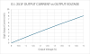
DIGIT DRIVERS
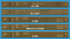
The GI 250 and GI 251 single-chip calculator circuits are manufactured in a PMOS process and its Digit Scanning Outputs are high-side PMOS transistors, an activated digit corresponds to a logical 1. We characterized here at the Datamath Calculator Museum the Digit Driver Output pin D15 of both a GI 250 and a GI 251 (Mask Revision F) and measured an output resistance of around 600 Ohm at an Output Voltage of -3.0 V.
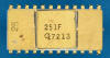
Note: GI 250 left thumbnail and GI 251F right thumbnail.
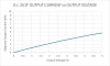
SEGMENT DRIVERS
The GI 250 and GI 251 single-chip calculator circuits are manufactured in a PMOS process and its Segment Outputs are high-side PMOS transistors, an activated segment corresponds to a logical 1. We characterized here at the Datamath Calculator Museum the Segment Driver Output pin SB of both a GI 250 and a GI 251 (Mask Revision F) and measured an output resistance of 1,000 Ohm at an Output Voltage of -3.0 V.
Note: GI 250 left thumbnail and GI 251F right thumbnail.
The Datamath Calculator Museum DCM-50A (PLAYGROUND) supports the Characterization of the GI 250 Product Family single-chip calculator circuits using the DCM-50A Playground C-500 Family Adapter mounted on top of the DCM-50A PG Frame Carrier and connected to the DCM50A Playground KBD102 Keyboard. The optional DCM-50A Playground Digilent I/O Extender supports Characterization and Reverse-engineering of GI 250 and GI 251 single-chip calculator circuits.
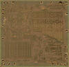
The GI 250 Product Family was manufactured in a 12 um metal gate PMOS process (metal width = 0.45 mil / 12.0 um, metal spacing = 0.35 mil / 9.0 um, diffusion width = 0.35 mil / 9.0 um, diffusion spacing = 0.30 mil / 7.5 um).
The die size of the GI 250/GI 251 is approximately 165 mils * 160 mils / 4.2 mm * 4.1 mm.
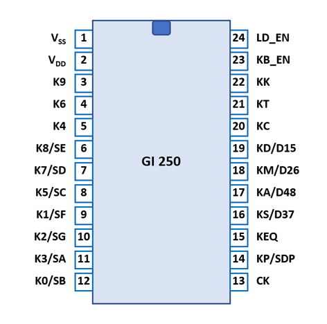
The GI 250 and GI 251 are using a standard 0.6” wide 24-pin CDIP (Ceramic Dual In-line Package with a 0.1” / 2.54 mm lead pitch).
| Pin | IO | Function | Pin | IO | Function |
| 1 | V | Common Voltage VSS | 24 | O | Lower Digits Enable |
| 2 | V | Negative Voltage VDD | 23 | O | Keyboard Enable |
| 3 | I | Key [9] | 22 | I | Key [K] |
| 4 | I | Key [6] | 21 | I | Key [T] |
| 5 | I | Key [4] | 20 | I | Key [C] |
| 6 | IO | Key [8], Segment E | 19 | IO | Key [÷], Digits 1&5 |
| 7 | IO | Key [7], Segment D | 18 | IO | Key [×], Digits 2&6 |
| 8 | IO | Key [5], Segment C | 17 | IO | Key [+], Digits 4&8 |
| 9 | IO | Key [1], Segment F | 16 | IO | Key [−], Digits 3&7 |
| 10 | IO | Key [2], Segment G | 15 | I | Key [=] |
| 11 | IO | Key [3], Segment A | 14 | IO | Key [.], Segment DP |
| 12 | IO | Key [0], Segment B | 13 | I | Clock |
| The Segment drivers A-G and DP (Decimal Point) are connected to the display in the pictured way. | 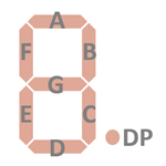 |
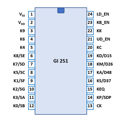
| Pin | IO | Function | Pin | IO | Function |
| 1 | V | Common Voltage VSS | 24 | O | Lower Digits Enable |
| 2 | V | Negative Voltage VDD | 23 | O | Keyboard Enable |
| 3 | I | Key [9] | 22 | I | Key [K] |
| 4 | I | Key [6] | 21 | O | Upper Digits Enable |
| 5 | I | Key [4] | 20 | I | Key [C] |
| 6 | IO | Key [8], Segment E | 19 | IO | Key [÷], Digits 1&5 |
| 7 | IO | Key [7], Segment D | 18 | IO | Key [×], Digits 2&6 |
| 8 | IO | Key [5], Segment C | 17 | IO | Key [+], Digits 4&8 |
| 9 | IO | Key [1], Segment F | 16 | IO | Key [−], Digits 3&7 |
| 10 | IO | Key [2], Segment G | 15 | I | Key [=] |
| 11 | IO | Key [3], Segment A | 14 | IO | Key [.], Segment DP |
| 12 | IO | Key [0], Segment B | 13 | I | Clock |
| The Segment drivers A-G and DP (Decimal Point) are connected to the display in the pictured way. | |
The keyboards of all calculators based on the GI 250 Product Family consist of 18 or 19 keys or contacts connected between the Keyboard-Enable output pin and 18 or 19 pins of the 24-pin Integrated Circuit package.
The GI 250 scans all 19 keys at the beginning of each display scanning cycle, indicated with a short pulse on its Keyboard-Enable output pin while briefly disabling all of its segments and digit output drivers.
Scanning of the 4-digit display is performed in D15 → D48 direction at a rate of about 830 Hz:
|
• State Time = 2 Clocks = 0.020 ms @ CK=100 kHz • Keyboard Time = 8 States = 0.160 ms @ CK=100 kHz • Digit Time = 13 States = 0.260 ms @ CK=100 kHz • Scan Time = Keyboard Time + 4 Digit Times (D15 to D48) = 1.2 ms @ CK=100 kHz |
The GI 251 scans all 18 keys at the beginning and the middle of each display scanning cycle, indicated with a short pulse on its Keyboard-Enable output pin while briefly disabling all of its segments and digit output drivers.
Scanning of the 8-digit display is performed in two 4-digit groups in D15 → D48 direction at a rate of about 420 Hz:
|
• State Time = 2 Clocks = 0.020 ms @ CK=100 kHz • Keyboard Time = 8 States = 0.160 ms @ CK=100 kHz • Digit Time = 13 States = 0.260 ms @ CK=100 kHz • Scan Time = Keyboard Time + 4 Digit Times (D15 to D48) + Keyboard Time + 4 Digit Times (D15 to D48) = 2.4 ms @ CK=100 kHz |
GI 250 |
||
| Pin# | KB_EN | |
| K0/SB | 12 | 0 |
| K1/SF | 9 | 1 |
| K2/SG | 10 | 2 |
| K3/SA | 11 | 3 |
| K4 | 5 | 4 |
| K5/SC | 8 | 5 |
| K6 | 4 | 6 |
| K7/SD | 7 | 7 |
| K8/SE | 6 | 8 |
| K9 | 3 | 9 |
| KP/SDP | 14 | . |
| KC | 20 | C |
| KK | 22 | K |
| KT | 21 | ↔ |
| KA/D48 | 17 | + |
| KS/D37 | 16 | − |
| KM/D26 | 18 | × |
| KD/D15B | 19 | ÷ |
| KEQ | 15 | = |
GI 251/251F |
||
| Pin# | KB_EN | |
| K0/SB | 12 | 0 |
| K1/SF | 9 | 1 |
| K2/SG | 10 | 2 |
| K3/SA | 11 | 3 |
| K4 | 5 | 4 |
| K5/SC | 8 | 5 |
| K6 | 4 | 6 |
| K7/SD | 7 | 7 |
| K8/SE | 6 | 8 |
| K9 | 3 | 9 |
| KP/SDP | 14 | . |
| KC | 20 | C |
| KK | 22 | K |
| KA/D48 | 17 | + |
| KS/D37 | 16 | − |
| KM/D26 | 18 | × |
| KD/D15B | 19 | ÷ |
| KEQ | 15 | = |
Calculators based on the GI 250 make use of 4-digit low-voltage VFDs (Vacuum Fluorescent Displays). Calculators based on the GI 251/251F make use of either 8-digit low-voltage VFDs or 8-digit LED (Light-Emitting-Diode) Displays with common cathode architecture.
If you have additions to the above datasheet please email: joerg@datamath.org.
© Joerg Woerner, July 5, 2025. No reprints
without written permission.