DATAMATH CALCULATOR MUSEUM
|
DATAMATH CALCULATOR MUSEUM |
General Instrument's last – and most successful – improvement of the original PICO1 design was introduced with the CZL-550 in 1974, supporting not only "trailing zero suppression" to reduced current consumption of the calculator but integrating segment drivers for the seven-segment LED display.
The combination of the CZL-550 and ITT’s B6249 demultiplexing digit driver chip allowed during the height of the "Calculator Wars" a very low Bill-of-Material – for some customers a higher priority than the flawed User Interface and Calculating Logic implementation of the once revolutionary PICO1 design dating back to 1971.
GI launched their C-593 and CF-593 chips in Summer 1973, boldly advertised as "socket-compatible" with Texas Instruments' TMS0803 and TMS0855, respectively and leading to the very successful C/CF-580, C/CF-590 and C/CF-680 Series of single-chip calculator circuits. General Instrument’s final calculator chip development was the C-680D/C-1680D series, integrating not only the segment drivers for LED displays, but also the digit drivers and hence allowing "true single-chip calculator designs".
QUICK-LINK to General Instrument Calculator Integrated Circuits.
| Type | Calculators | Keyboard | Constant (M-D-A-S) |
Digits Math |
Digits Display |
Fixed DP | Rounding | Special Functions |
Seg./Dig. Blanking |
(6,7,9) Font |
Entry Overflow |
Calculating Overflow |
| CZL-550 | Radofin Model 2200 | [+][−][=] | 2-2-2-2 | 8 | 4 + 4 Alternating |
Float 10-20-1079 |
None | Constant Number Constant Function |
S1 of 13 S1 of 13 |
| Description | Comments | |
| Architecture | Single-chip Calculator | First Generation RISC Architecture |
| Category | Register Processor | |
| Related | CZ-550 | Standard Digit Drivers |
| ROM Size | 3,146 Bits | 72 Words * 27 to 63 Bits |
| RAM Size | 141 Bits | 3 Registers * 44 Bits (11 Digits) 1 Register * 9 bits |
| Outputs | 4 Digits + 3
Control 8 Segments |
Standard Digit Drivers LED Segment Drivers |
| Inputs | 18 Keyboard | Direct Keyboard Inputs |
| Revision | Products | First Prototypes | Comments |
| CZL-550 | Gilette GPA Prototype | tbd | Mask: 1972 78180 |
| CZL-550 Rev B | Radofin Model 2200 | tbd | Mask: 1974 90 - 78190 |
Capacity: Up to 8 digits positive and 7 digits negative
Logic: Algebraic Chain Logic with Constant
[C] [2] [x] [3] [+] [4] [x] [5] [=] → '50. '
Number Entry: Right-justified number entry without leading-zero suppression, entering up to 79 digits before the decimal point or 19 digits after the decimal point is registered but in the display ignored
[C] [1] → '00000001', [2] [3] [4] [5] [6] [7] [8] [9] [0] → '12345678', [:] [1] [0] [0] [0] [=] → '1234567.8'
[C] [0] [.] → '00000000.', [0] [0] [0] [0] [0] [0] [0] [1] [2] [3] → '0.0000123', [x] → '0.0000000', [1] [0] [0] [0] → '00001000', [=] → '0.0000123'
Decimal Point: Last entered decimal point is used
[C] [1] [.] [2] [.] [3] → '0000012.3'
Fixed Decimal Point: Fixed decimal point arithmetic is not supported
Decimal Alignment: Decimal alignment is supported for additions and subtractions
[C] [0] [.] [4] [5] [+] [0] [.] [5] [5] [=] → '1.0000000'
Clear: No automatic power-up clear implemented. [C] key before entering a number clears the whole calculator, [C] key before entering a function clears last entry of a number
[C] [1] [+] [2] [C] [3] [=] → '3. '; [C] [1] [+] [2] [C] [+] [3] [=] → '4. '
Change Sign: Not supported. When performing multiplication or division, a negative value can only be assigned to the first number by pressing the [C] [0] [−] key before entering the number
[C] [0] [−] [2] [x] [3] [=] → '-6. '; [C] [0] [−] [2] [x] [−] [3] [=] → '-5. '
Number Display: Left-justified number display with trailing-zero suppression
[C] [1] [.] [2] [3] [x] [1] [0] [0] [=] → '123. '
[C] [1] [.] [2] [3] [:] [1] [0] [0] [=] → '0.0123 '
Negative Numbers: Negative numbers are shown with '-' in the leftmost position
Calculating Overflow: An overflow shows the result without the decimal point for numbers up to ±9.9999999 * 1079 with the 8 (for positive and negative numbers) significant digits preserved
[C] [1] [2] [3] [4] [5] [x] [1] [2] [3] [4] [5] [=] → '15239902', [:] [1] [0] [0] [0] [=] → '152399.02'
[C] [1] [2] [3] [4] [5] [0] [0] [0] [x] [1] [2] [3] [4] [5] [0] [0] [0] [=] → '15239902', [:] [1] [0] [0] [0] [=] → '15239902', [:] [1] [0] [0] 0] [=] → '15239902', [:] [1] [0] [0] [0] [=] → '152399.02'
Calculating Underflow: An underflow shows '0. ' for numbers down to ±1.0 * 10-20 with the 8 (for positive and negative numbers) significant digits preserved
[C] [0] [.] [0] [0] [0] [1] [:] [7] [0] [0] [0] [0] [=] → '0. ', [x] [1] [0] [0] [0] [=] → '0.0000014', [x] [1] [0] [0] [0] [=] → '0.0014285', [x] [1] [0] [0] [0] [=] → '1.4285714'
Divide By Zero: A division of a positive or negative number by zero results in an erratic (endless counting) 8 digits (positive) or 7 digits (negative) display with all decimal points lit and is only recoverable using the [C] key
[C] [1] [:] [0] [=] → '?.?.?.?.?.?.?.?.'; [C] [0] [−] [1] [:] [0] [=] → '.?.?.?.?.?.?.?.'
Timeout: Not supported
Rounding: Rounding of displayed calculating results is not supported
[C] [2] [0] [:] [3] [=] → '6.6666666'
Constant: Constant function can be enabled in two different modes (Constant Number or Constant Function) with a dedicated key for multiplication, division, addition and subtraction
[C] [3] [=] [K] → '3. ', [1] [x] → '3. ', [1] [:] → '0.3333333', [1] [+] → '4. ', [1] [−] → '-2. ',
[C] [3] [x] [K] → '3. ', [2] [=] → '6. ', [3] [=] → '9. ', [=] → '9. '
[C] [3] [:] [K] → '3. ', [2] [=] → '0.6666666', [3] [=] → '1. ', [=] → '0.3333333'
[C] [3] [+] [K] → '3. ', [2] [=] → '5. ', [3] [=] → '6. ', [=] → '9. '
[C] [3] [−] [K] → '3. ', [2] [=] → '1. ', [3] [=] → '0. ', [=] → '-3. '
Reciprocal Function: The reciprocal function is implemented using the [:] key directly followed by the [K] and [=] keys
[C] [4] [:] [K] [=] [=] → '0.25 '
Known Calculator Logic Bugs:
Exponent Rollover Bug: Calculations are allowed for numbers between ±1.0 * 10-20 and ±9.9999999 * 1079. Smaller numbers result in an exponents rollover to a large number and vice versa
[C] [0] [.] [0] [0] [0] [0] [0] [0] [1] [x] [K] → '0.0000001', [1] [.] [2] [3] [=] → '0.0000001' (1.23 * 10-7), [=] → '0. ' (1.23 * 10-14), [=] → '12300000' (1.23 * 10-21 # 1.23 * 1079), eleven times [=] → '123. ' (1.23 * 102)
| Item | Min | Typ | Max | Unit | Comments |
| VSS | 0 | V | |||
| VDD | -15.0 | V | |||
| IDD | 10.0 | mA | REXT = 100k Ohm,
Segment- and Digit-Driver Load 100k Ohm to VDD |
||
| VOUT | -18 | -15 | 0.3 | V | VFD Output Voltage through 100k Ohm Resistors |
| VIN | -18 | -15 | 0.3 | V | Input Voltage through 100k Ohm Resistors |
| ION1 (Digit) | -4.0 | mA | VOT = -2.0 V | ||
| ION2 (Digit) | -7.5 | mA | VOT = -4.0 V | ||
| ION1 (Segment) | -15.0 | mA | VOT = -2.0 V | ||
| ION2 (Segment) | -25.0 | mA | VOT = -4.0 V | ||
| CK | 100 | kHz |
KEYBOARD AND DISPLAY SCANNING
The CZL-550 uses a keyboard scanning matrix with all of its 18 keys connected directly to a corresponding pin, while the common signal is connected to a dedicated Keyboard Enable pin. Six of the 18 keys are using dedicated Key Input pins, four are shared with the Digit Outputs and eight are shared with the Segment Outputs. To allow for the use of the Digit and Segment Output pins as Key Input pins, the CZL-500 is blanking the display completely before each Display Scanning Cycle while reading the keyboard.
The CZL-550 is using two dedicated 'Lower Digits Enable' and 'Upper Digits Enable' pins, signaling if the lower four Digits D1 to D4 or the higher four Digits D5 to D8 are output on the shared D15, D26, D37, and D48 pins. The CZL-550 is outputting the lower and higher digit groups with each Display Scanning Cycle in an alternating pattern and blanking the display completely while reading the keyboard.INTER-DIGIT BLANKING
The CZL-550 single-chip calculator circuit is blanking its Digit and Segment Outputs for one of thirteen State Times at the beginning of each of the four Digit Times. During the Keyboard Time, the Digit and Segment Outputs are blanked for eight State Times.
DIGIT DRIVERS
The CZL-550 single-chip calculator circuit is manufactured in a PMOS process and its Digit Scanning Outputs are high-side PMOS transistors, an activated digit corresponds to a logical 1. We characterized here at the Datamath Calculator Museum the Digit Driver Output pin D15 of a CZL-550 (Mask Revision tbd) and measured an output resistance of around 500 Ohm at an Output Voltage of -3.0 V.
SEGMENT DRIVERS
The CZL-550 single-chip calculator circuit is manufactured in a PMOS process and its Segment Outputs are high-side PMOS transistors, an activated segment corresponds to a logical 1. We characterized here at the Datamath Calculator Museum the Segment Driver Output pin SB of a CZL-550 (Mask Revision tbd) and measured an output resistance of 150 Ohm at an Output Voltage of -3.0 V, allowing to directly drive the segments of a multiplexed LED Display.
The Datamath Calculator Museum DCM-50A (PLAYGROUND) supports the Characterization of the CZL-550 single-chip calculator circuit using the DCM-50A Playground C-500 Family Adapter mounted on top of the DCM-50A PG Frame Carrier and connected to the DCM50A Playground KBD102 Keyboard. The optional DCM-50A Playground Digilent I/O Extender supports Characterization and Reverse-engineering of CZL-550 single-chip calculator circuits.
The CZL-550 was manufactured in a 9 um metal gate PMOS process (metal width = 0.35 mil / 9.0 um, metal spacing = 0.35 mil / 9.0 um, diffusion width = 0.30 mil / 7.5 um, diffusion spacing = 0.30 mil / 7.5 um).
The die size of the CZL-550 is approximately 155 mils * 150 mils / 4.0 mm * 3.8 mm.
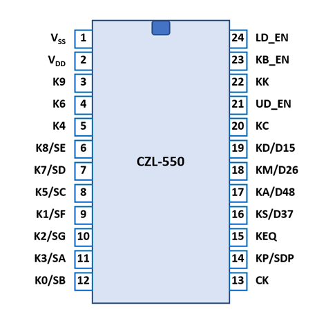
The CZL-550 is using a standard 0.6” wide 24-pin CDIP (Ceramic Dual In-line Package with a 0.1” / 2.54 mm lead pitch) or 24-pin DIP (Dual In-line Package with a 0.1” / 2.54 mm lead pitch.
| Pin | IO | Function | Pin | IO | Function |
| 1 | V | Common Voltage VSS | 24 | O | Lower Digits Enable |
| 2 | V | Negative Voltage VDD | 23 | O | Keyboard Enable |
| 3 | I | Key [9] | 22 | I | Key [K] |
| 4 | I | Key [6] | 21 | O | Upper Digits Enable |
| 5 | I | Key [4] | 20 | I | Key [C] |
| 6 | IO | Key [8], Segment E | 19 | IO | Key [÷], Digits 1&5 |
| 7 | IO | Key [7], Segment D | 18 | IO | Key [×], Digits 2&6 |
| 8 | IO | Key [5], Segment C | 17 | IO | Key [+], Digits 4&8 |
| 9 | IO | Key [1], Segment F | 16 | IO | Key [−], Digits 3&7 |
| 10 | IO | Key [2], Segment G | 15 | I | Key [=] |
| 11 | IO | Key [3], Segment A | 14 | IO | Key [.], Segment DP |
| 12 | IO | Key [0], Segment B | 13 | I | Clock |
| The Segment drivers A-G and DP (Decimal Point) are connected to the display in the pictured way. | 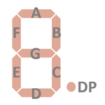 |
The keyboards of all calculators based on the CZL-550 consist of 18 keys or contacts connected between the Keyboard-Enable output pin and 18 pins of the 24-pin Integrated Circuit package.
The CZL-550 is scanning all 18 keys at the beginning and the middle of each display scanning cycle, indicated with a short pulse on its Keyboard-Enable output pin while briefly disabling all of its segments and digit output drivers.
Scanning of the 8-digit display is performed in two 4-digit groups in D15 → D48 direction at a rate of about 420 Hz:
|
• State Time = 2 Clocks = 0.020 ms @ CK=100 kHz • Keyboard Time = 8 States = 0.160 ms @ CK=100 kHz • Digit Time = 13 States = 0.260 ms @ CK=100 kHz • Scan Time = Keyboard Time + 4 Digit Times (D15 to D48) + Keyboard Time + 4 Digit Times (D15 to D48) = 2.4 ms @ CK=100 kHz |
CZL-550 |
||
| Pin# | KB_EN | |
| K0/SB | 12 | 0 |
| K1/SF | 9 | 1 |
| K2/SG | 10 | 2 |
| K3/SA | 11 | 3 |
| K4 | 5 | 4 |
| K5/SC | 8 | 5 |
| K6 | 4 | 6 |
| K7/SD | 7 | 7 |
| K8/SE | 6 | 8 |
| K9 | 3 | 9 |
| KP/SDP | 14 | . |
| KC | 20 | C |
| KK | 22 | K |
| KA/D48 | 17 | + |
| KS/D37 | 16 | − |
| KM/D26 | 18 | × |
| KD/D15B | 19 | ÷ |
| KEQ | 15 | = |
Calculators Calculators based on the CZL-550 make use of 8-digit LED (Light-Emitting-Diode) Displays with common cathode architecture.
If you have additions to the above datasheet please email: joerg@datamath.org.
© Joerg Woerner, October 22, 2025. No reprints
without written permission.