DATAMATH CALCULATOR MUSEUM
|
DATAMATH CALCULATOR MUSEUM |
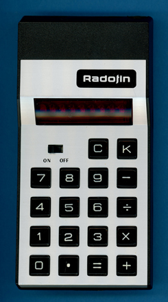
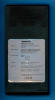
Radofin Model 2200
| Date of introduction: | March 1974 | Display technology: | LED-stick |
| New price: | Display size: | 8 | |
| Size: | 5.3" x 2.7" x
0.95" 135 x 69 x 24 mm3 |
||
| Weight: | 3.5 ounces, 100 grams | Serial No: | 15171 |
| Batteries: | 9V Alkaline | Date of manufacture: | mth 05 year 1974 |
| AC-Adapter: | Origin of manufacture: | Hong Kong | |
| Precision: | 8 | Integrated circuits: | General Instrument CZL-550 |
| Logic: | Chain Logic | Displays: | HP 5082-7448 |
| Memories: | |||
| Program steps: | Courtesy of: | Joerg Woerner | |
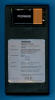
| Download manual: | |
![]()
 Radofin
electronics of London, United Kingdom was founded early in the 1970s and started
distributing electronic calculators before entering in 1976 the market of
electronic games, too. Most of their later products were manufactured by Radofin Electronics (Far East)
in Hong Kong.
Radofin
electronics of London, United Kingdom was founded early in the 1970s and started
distributing electronic calculators before entering in 1976 the market of
electronic games, too. Most of their later products were manufactured by Radofin Electronics (Far East)
in Hong Kong.
We acquired this Radofin Model 2200 calculator
in 2025 on our quest to complete the
Characterization of Single-Chip Calculator Circuits
of General Instrument's C-500 Product Family of Single-chip Calculator Circuits.
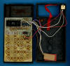
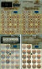
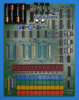
 Dismantling
the featured Radofin Model 2200 calculator manufactured in May 1974 in Hong Kong
reveals a highly cost-optimized design based on a double-sided printed circuit board
(PCB) for the electronics and powered by a 9-Volt battery or an external power adapter.
Dismantling
the featured Radofin Model 2200 calculator manufactured in May 1974 in Hong Kong
reveals a highly cost-optimized design based on a double-sided printed circuit board
(PCB) for the electronics and powered by a 9-Volt battery or an external power adapter.
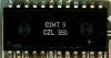
 The
PCB is centered around a General Instrument CZL-550 single-chip calculator
circuit and supported by an ITT 7105 "demultiplexing" digit driver for the LED
display. Two additional resistors and a capacitor are used for the keyboard
interface and power supply. A small DC/DC converter module is glued to the backside of the
calculator housing, it is generating the
different supply voltages for the CZL-550 and its clock signal.
The
PCB is centered around a General Instrument CZL-550 single-chip calculator
circuit and supported by an ITT 7105 "demultiplexing" digit driver for the LED
display. Two additional resistors and a capacitor are used for the keyboard
interface and power supply. A small DC/DC converter module is glued to the backside of the
calculator housing, it is generating the
different supply voltages for the CZL-550 and its clock signal.
 To
gain some knowledge about the differences between the CZL-550 located in this Radofin 2200, the
CZ-550 located in the calfax
800CD and the
C-550 used with the Interton PC 2008, we
decided here at the Datamath Calculator Museum to give it a "Teardown
Treatment" and sharing our findings accordingly.
To
gain some knowledge about the differences between the CZL-550 located in this Radofin 2200, the
CZ-550 located in the calfax
800CD and the
C-550 used with the Interton PC 2008, we
decided here at the Datamath Calculator Museum to give it a "Teardown
Treatment" and sharing our findings accordingly.
 Calculating Unit:
The CZL-550 used with the Radofin Model 2200 is a member of the fourth generation of
General Instrument single-chip calculator circuits and traces back to the famous
PICO1 introduced already in 1971:
Calculating Unit:
The CZL-550 used with the Radofin Model 2200 is a member of the fourth generation of
General Instrument single-chip calculator circuits and traces back to the famous
PICO1 introduced already in 1971:
|
• 1971: GEN1 GI 250 (76250) and GI 251/251F (76251) – 4-digit display or 4-digit multiplexed 8-digit display, 25 Volt • 1972: GEN1 C-500 (76251) – 4-digit multiplexed 8-digit display, 25 Volt • 1973: GEN2 C-550/CZ-550 - 4-digit multiplexed 8-digit display, 15 Volt • 1973: GEN3 C-560/C-570 - 8-digit display, 15 Volt • 1974: GEN4 CZL-550 – 8-digit display, trailing zero suppression, integrated segment drivers, 15 Volt |
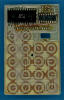
 Display:
The featured Radofin Model 2200 calculator manufactured
in May 1974 makes use of a Hewlett Packard 5082-7448 Nine-Digit display module
with 8 Seven-Segment displays chips bonded onto a PCB and magnified with a clear
plastic lens. The leftmost display position is not populated. The display module
is connected with 16 pins to the PCB.
Display:
The featured Radofin Model 2200 calculator manufactured
in May 1974 makes use of a Hewlett Packard 5082-7448 Nine-Digit display module
with 8 Seven-Segment displays chips bonded onto a PCB and magnified with a clear
plastic lens. The leftmost display position is not populated. The display module
is connected with 16 pins to the PCB.
![]() Display Driver: Early single-chip calculator circuits like the PICO1,
Mostek's MK6010 or Texas Instruments'
TMS0100 didn't include any display drivers
and left the choice of display technology and necessary interface circuitry to
the designers of the electronic calculators. The PMOS (p-channel Metal–oxide
Semiconductor) technology used with these chips was neither compatible with
Vacuum Fluorescent Displays (VFDs) nor with Led Emitting Diode (LED) Displays:
Display Driver: Early single-chip calculator circuits like the PICO1,
Mostek's MK6010 or Texas Instruments'
TMS0100 didn't include any display drivers
and left the choice of display technology and necessary interface circuitry to
the designers of the electronic calculators. The PMOS (p-channel Metal–oxide
Semiconductor) technology used with these chips was neither compatible with
Vacuum Fluorescent Displays (VFDs) nor with Led Emitting Diode (LED) Displays:
| • VF Display - Operating voltage (30 to 45 V) higher than chip voltage (15 to 25 V) • LED Displays - Operating current (10 to 50 mA per digit) higher than chip output current (1 to 5 mA) |
Progress with both display technology and chip technology allowed around 1972/1973 the direct connection of low-voltage (< 35 Volts) VF Displays to single-chip calculator circuits with modified "high-side" segment and digit output drivers to withstand up to -35 Volts. In a next step, around 1973, the used PMOS chip technology allowed beefier "high-side" segment drivers while the LED displays exhibited increased efficiency, meaning they could be operated with lower currents. The digit drivers still used external "low-side" drivers. Rockwell introduced in June 1974 with the A5300 Product Family the first single-chip calculator circuits with LED (Light-Emitting-Diode) Direct-Drive capability, integrating not only the segment drivers but the digit drivers, too.
The General Instrument CZL-550 chip uses only 4 digit outputs, labeled D15, D26, D37, and D48, requiring an external "demultiplexer" to operate an 8-digit display. The dismantled Radofin Modell 2200 calculator uses the ITT 7105 8-Digit Driver for a very simple and straightforward approach to interface with the LED display:
| • The for D15, D26, D37, and D48 inputs of the ITT 7105 are connected directly to the digit outputs of the CZL-550 chip • The /D input of the ITT 7105 is connected directly to the UD_EN output of the CZL-550, selecting the upper or lower digit groups • The D1 to D8 outputs of the ITT 7105 are connected to the Common Cathodes D1 to D8 of the LED display (D9 is not used) • The A to G and DP segments (Anodes) of the LED display are driven directly from the CZL-550 chip |
Clock: The CZL-550 single-chip calculator circuit of the Radofin Model 2200 is
operated with a frequency of about 92 kHz.
Power Supply: The Radofin Model 2200 calculator is powered with a disposable
9-Volt alkaline battery or an external 9 Volt power adapter
and uses a simple DC/DC converter to generate an additional negative voltage for
the CZL-550:
|
• VSS - Positive supply for CZL-550 (+9.0 V) from battery • GND - Negative supply for LED Display (0 V) from battery • VDD - Negative supply for CZL-550 (-4.7 V) from DC/DC converter |
We measured the operating current of the featured Radofin Model 2200 calculator for two different cases:
| Mode | Display | Current VBAT = 9.0 V |
Clock Frequency |
| Calculating | 0 | 20 mA | 92 kHz |
| Calculating | 88888888. | 50 mA | 92 kHz |
Calculating the power consumption at 9 Volts for the Radofin Model 2200 results in about 180 mW displaying a '0' and about 450 mW with all segments illuminated. An unusual high idle value, a similar designed MBO Expert, centered around a TMS0833 single-chip calculator circuit, clocked in at 120 mW displaying a '0' but consumed about 500 mW with all segments illuminated, too.
Keyboard:
The keyboard of the Radofin Model 2200 uses 18
snap action switches mounted directly on the PCB of the calculator and a sliding
switch for power.
 Here
at the Datamath Calculator Museum we use
the DCM-50A Platform to
Characterize and
Reverse-engineer
Single-chip Calculator Circuits. Many designs of electronic calculators do not
use all features of their calculator brains and it would be difficult to unleash
the full potential of the calculator chips in these cases. Additionally are
electronic calculators "closed systems" with limited flexibility to measure
signals, change voltages or clock frequencies, provide additional input keys or
even change the display technology or specifications additional digits. Core
idea of the DCM-50A is providing a generic platform to access all features of a
single-chip calculator circuit and with the
DCM-50A (PLAYGROUND) we
increased the scope from Texas Instruments products to offerings from their
competitors in the 1970s, namely AMI, Cal-Tex, Commodore/MOS Technology,
Electronic Arrays, General Instrument, Hitachi, Litronix, Matsushita,
Mitsubishi, Mostek, National Semiconductor, NEC, Omron, RFT, Rockwell, Sharp,
Toshiba, and Western Digital.
Here
at the Datamath Calculator Museum we use
the DCM-50A Platform to
Characterize and
Reverse-engineer
Single-chip Calculator Circuits. Many designs of electronic calculators do not
use all features of their calculator brains and it would be difficult to unleash
the full potential of the calculator chips in these cases. Additionally are
electronic calculators "closed systems" with limited flexibility to measure
signals, change voltages or clock frequencies, provide additional input keys or
even change the display technology or specifications additional digits. Core
idea of the DCM-50A is providing a generic platform to access all features of a
single-chip calculator circuit and with the
DCM-50A (PLAYGROUND) we
increased the scope from Texas Instruments products to offerings from their
competitors in the 1970s, namely AMI, Cal-Tex, Commodore/MOS Technology,
Electronic Arrays, General Instrument, Hitachi, Litronix, Matsushita,
Mitsubishi, Mostek, National Semiconductor, NEC, Omron, RFT, Rockwell, Sharp,
Toshiba, and Western Digital.
On our quest to document Pico Electronics' PICO1 Chip and its
many descendants like the General Instrument C-500, C-550, CZ-550, C-560, C-570 and
CZL-550, we developed here at the Datamath Calculator Museum three additional
tools for our DCM-50A (PLAYGROUND):
| • DCM-50A
(PLAYGROUND) C-500
Family Adapter: Daughter Board for the
DCM-50A (PLAYGROUND)
Frame Carrier for
General Instrument's C-500 Portfolio • DCM-50A (PLAYGROUND) KBD102 Keyboard: Keyboard with 20 individual keys to support the PICO1-style keyboard reading • DCM-50A (PLAYGROUND) Digilent I/O Extender: Plug-In Board to add six additional Input Signals for the Digilent Discovery |
Comparing the Calculator Logic Implementation of the CZL-550 retrieved from the featured Radofin Model 2200 calculator with the Calculator Logic Implementation of the CZ-550 chip reveals no differences.
Comparing the Segment Driver Output Characteristics of the CZ-550 with the Segment Driver Output Characteristics of the CZL-550 reveals a substantial difference and makes us wonder why the calfax 800CD omits external segment drivers.
Don't miss the "Picolator" on the German Richi's Lab site, an Emulator for General Instrument's C-550 single-chip calculator circuit - still using the PICO1 program code from the original GI 250 chip.
If you have additions to the above article please email: joerg@datamath.org.
© Joerg Woerner, August 16, 2025. No reprints without written permission.