DATAMATH CALCULATOR MUSEUM
|
DATAMATH CALCULATOR MUSEUM |
Royal Model 91K (UA122)
| Date of introduction: | 1975 | Display technology: | Fluorescent |
| New price: | Display size: | 8 + Sign | |
| Size: | 4.7" x 2.9" x
0.85" 120 x 73 x 22 mm3 |
||
| Weight: | 4.2 ounces, 119 grams | Serial No: 046684 | 022109 |
| Batteries: | 4*AAA | Date of manufacture: | mth 09 year 1975 |
| AC-Adapter: | Origin of manufacture: | Japan | |
| Precision: | 8 | Integrated circuits: | NEC µPD947 |
| Logic: | Adding Machine | Displays: | Futaba 9-ST-12 |
| Memories: | 1 | ||
| Program steps: | Courtesy of: | Joerg Woerner |

![]() Litton Industries,
headquartered in Beverly Hills, California, acquired in 1958
Monroe Calculating Machine Company, an American manufacturer of mechanical calculators.
In 1966 Litton acquired Imperial Typewriter Company Ltd, a very successful manufacturer of typewriters and merged it with its own
Royal Typewriter division. In 1969
the conglomerate was further growing with the acquisition of
Triumph-Adler, the merger of UK Triumph Cycle Company and Adler, a German
manufacturer of bicycles, typewriters, sewing machines and calculators. Early
in the 1970s, Litton sold, depending on the region, electronic calculators under
five different brands: Adler, Imperial, Monroe, Royal and Triumph.
Litton Industries,
headquartered in Beverly Hills, California, acquired in 1958
Monroe Calculating Machine Company, an American manufacturer of mechanical calculators.
In 1966 Litton acquired Imperial Typewriter Company Ltd, a very successful manufacturer of typewriters and merged it with its own
Royal Typewriter division. In 1969
the conglomerate was further growing with the acquisition of
Triumph-Adler, the merger of UK Triumph Cycle Company and Adler, a German
manufacturer of bicycles, typewriters, sewing machines and calculators. Early
in the 1970s, Litton sold, depending on the region, electronic calculators under
five different brands: Adler, Imperial, Monroe, Royal and Triumph.
Royal Typewriters and its sister company Triumph-Adler were sold in 1986 to Olivetti and is since September 2004 a private American company again and today known as Royal Consumer Information Products Inc.
The featured Royal Model 91K calculator was manufactured by Omron in Japan and is a member of a design series that comes in three different sizes:
| • Small - Royal Model 80K et al. • Medium - Royal Model 90K, Model 91K et al. • Large - Imperial Model 12HT et al. |


 Dismantling
the featured Royal Model 91K calculator manufactured in September 1975 by Omron in Japan
reveals a very compact design based on a single-sided printed circuit board
(PCB) for the main electronics, a single-sided PCB for the keyboard and powered
by four disposable 1.5 Volts batteries or an external power adapter.
Dismantling
the featured Royal Model 91K calculator manufactured in September 1975 by Omron in Japan
reveals a very compact design based on a single-sided printed circuit board
(PCB) for the main electronics, a single-sided PCB for the keyboard and powered
by four disposable 1.5 Volts batteries or an external power adapter.
 The
Main-PCB is centered around a µPD947
single-chip calculator circuit manufactured by NEC and the few other remaining
components on the PCB are mainly used to generate the different supply voltages
for the µPD947 and Vacuum Fluorescent Display (VFD) and to bias the anodes and
grids of the display with respect to its filament.
The
Main-PCB is centered around a µPD947
single-chip calculator circuit manufactured by NEC and the few other remaining
components on the PCB are mainly used to generate the different supply voltages
for the µPD947 and Vacuum Fluorescent Display (VFD) and to bias the anodes and
grids of the display with respect to its filament.
![]() To gain some knowledge about the differences
between the µPD947 located in this Royal
Model 91K and the µPD946 used with the
Royal RSC-40, we decided here at the Datamath Calculator Museum to give the featured calculator
a full "Teardown Treatment" and share our findings accordingly.
To gain some knowledge about the differences
between the µPD947 located in this Royal
Model 91K and the µPD946 used with the
Royal RSC-40, we decided here at the Datamath Calculator Museum to give the featured calculator
a full "Teardown Treatment" and share our findings accordingly.
![]() Calculating Unit:
The µPD947 located in the featured calculator is a variation of
the µPD946, an enhanced version of the µPD940
- one of the first
"true" single-chip calculator circuits designed by NEC. The µPD946 features
like the µPD940 an integrated
clock oscillator and both its segment and digit output drivers are interfacing
directly with low-voltage VFDs up to 30 Volts. Here at the Datamath Calculator
Museum we don't qualify NEC's earlier µPD271 as a true single-chip calculator circuit, it
is using with the µPD261 an external segment decoder and driver chip for the
calculator display.
Calculating Unit:
The µPD947 located in the featured calculator is a variation of
the µPD946, an enhanced version of the µPD940
- one of the first
"true" single-chip calculator circuits designed by NEC. The µPD946 features
like the µPD940 an integrated
clock oscillator and both its segment and digit output drivers are interfacing
directly with low-voltage VFDs up to 30 Volts. Here at the Datamath Calculator
Museum we don't qualify NEC's earlier µPD271 as a true single-chip calculator circuit, it
is using with the µPD261 an external segment decoder and driver chip for the
calculator display.
![]() Display:
The featured Royal Model 91K calculator manufactured
in September 1975 makes use of an 9-Digit low-voltage VFD manufactured by Futaba and
known as Type 9-ST-12, soldered with its 19 pins directly to the
Main-PCB.
Display:
The featured Royal Model 91K calculator manufactured
in September 1975 makes use of an 9-Digit low-voltage VFD manufactured by Futaba and
known as Type 9-ST-12, soldered with its 19 pins directly to the
Main-PCB.
Display Driver: The term "low-voltage" Vacuum Fluorescent Display might
be misleading when used together with a calculator powered by four 1.5 Volt
batteries. Common VFDs used with portable electronic calculators are usually
operated around 30 Volts, significantly higher than the 10 to 15 Volts operating
voltage of single-chip calculator circuits used in the 1970s. While the first
generation of Texas Instruments TMS0100 single-chip calculator circuits lacked
any display drivers and left the choice of display technology to their
customers, focused the second generation products mainly on Light-Emitting Diode
(LED) technology. In or around 1974, most Western calculator designs still
relied on rather expensive LED technology but Japanese companies like Casio,
Sanyo, Sharp and Toshiba started to leverage the lower manufacturing costs of
VFDs, instead. Texas Instruments introduced in 1974 consequently with the
TMS0850 their first product series focused on battery operated VFD calculators
and modified the integrated segment and digit output drivers to withstand up to
-35 Volts. NEC on the other hand entered the marked of single-chip calculator
circuits in 1973/1974 and focused immediately on compatibility with VFDs. The
µPD947 chips are manufactured in PMOS technology, meaning the
output transistors are "high-side" switching and the most positive voltage of
the chip is labeled VSS for 0 Volt, all other voltages in the
calculator are consequently negative with respect to VSS. Multiplexed
low-voltage VFDs need a voltage difference between its filament and the grids
and anodes of the numbers of around 30 Volts to light up and to avoid "ghosting"
while scanning, the deactivated grids and anodes should be slightly lower than
the filament voltage. An elegant and very common solution is found with this
Royal Model 91K calculator, too. The grids and anodes of the VFD are "pulled-down"
with 17 resistors (150k Ohm) to around -27 Volts, the filament is biased to
around -23 Volts (Zener Diode) and the µPD947 switches the
relevant grids and anodes to around 0 Volt to lit them up.
Clock: The Royal Model 91K makes use of the internal clock
oscillator of the µPD946 Series of single-chip calculator circuits, we identified a
capacitor with
1,500 pF connected between Pin 28 (CLK/CEXT) of the µPD947 and the
positive
VSS power supply line, resulting in a
clock frequency of about 65 kHz.
Power Supply: The Royal Model 91K calculator is powered with
four disposable AAA-sized 1.5 Volt batteries or an external 6 Volt power adapter and uses a
complex DC/DC converter to
generate a total of four voltages:
|
• VDD - Negative supply for
µPD947 (-4.6 V) • VGG - Negative supply for µPD941 (-9.1 V) • VPP - Negative supply for VFD anodes and grids (-26.5 V) • VFIL - AC supply for VFD Filament (2.5 V) |
We measured the operating current of the featured Royal Model 91K calculator for two different cases:
| Mode | Display | Current VBAT = 6.0 V |
Clock Frequency |
| Calculating | 0. | 20 mA | 63 kHz |
| Calculating | 88888888. | 36 mA | 63 kHz |
Calculating the power consumption at 6 Volts for the Royal Model 91K results in about 120 mW displaying a '0.' and about 220 mW with all segments but the minus sign illuminated. A very interesting result, a Canon LE-84 calculator with a LED display and using four disposable 1.5 Volt Alkaline batteries and a DC/DC converter for its TMS0801 chip clocks in at around 100 mW displaying a '0.' and 320 mW with all segments lit; showing both an advantage and disadvantage of LED-based calculators versus their VFD-based counterparts:
|
• LED: Only illuminated segments draw current - advantage LED while displaying
'0.' • VFD: Filament uses always current, segment currents are almost negligible - advantage VFD while displaying '88888888.' |

 Keyboard:
The keyboard assembly of the Royal Model 91K with the Date code
50.8.28 was manufactured by GICO in August 1975 and uses 3 sliding switches and
24 spring-supported
plastic keys pushing small fingers on stamped sheet-metal pieces against
contacts etched on a single-sided phenolic PCB.
Keyboard:
The keyboard assembly of the Royal Model 91K with the Date code
50.8.28 was manufactured by GICO in August 1975 and uses 3 sliding switches and
24 spring-supported
plastic keys pushing small fingers on stamped sheet-metal pieces against
contacts etched on a single-sided phenolic PCB.
 While
most single-chip calculator circuits are using their digit driver outputs to
scan the keyboard matrix, decided NEC to utilize with the µPD946 Series the
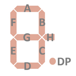
so-called segment scanning technology. The first part of a complete scanning
cycle outputs the corresponding display information for the nine digits on the
segment outputs, and the second part blanks the display and scans the segment
outputs A to H and DP for possible keyboard actions. A 10th keyboard row
is connected directly to the VSS power supply line to accommodate
keyboards with up to 40 keys, greatly improving the limit of 24 contacts of the
µPD940 Series. The layout of the keyboard
assembly of the featured Royal Model 91K calculator shows consequently an arrangement with
10 keyboard scan lines and 4 keyboard return lines.
While
most single-chip calculator circuits are using their digit driver outputs to
scan the keyboard matrix, decided NEC to utilize with the µPD946 Series the
so-called segment scanning technology. The first part of a complete scanning
cycle outputs the corresponding display information for the nine digits on the
segment outputs, and the second part blanks the display and scans the segment
outputs A to H and DP for possible keyboard actions. A 10th keyboard row
is connected directly to the VSS power supply line to accommodate
keyboards with up to 40 keys, greatly improving the limit of 24 contacts of the
µPD940 Series. The layout of the keyboard
assembly of the featured Royal Model 91K calculator shows consequently an arrangement with
10 keyboard scan lines and 4 keyboard return lines.
 Here
at the Datamath Calculator Museum we use
the DCM-50A Platform to
Characterize and
Reverse-engineer
Single-chip Calculator Circuits. Many designs of electronic calculators do not
use all features of their calculator brains and it would be difficult to unleash
the full potential of the calculator chips in these cases. Additionally are
electronic calculators "closed systems" with limited flexibility to measure
signals, change voltages or clock frequencies, provide additional input keys or
even change the display technology or specifications additional digits. Core
idea of the DCM-50A is providing a generic platform to access all features of a
single-chip calculator circuit and with the
DCM-50A (PLAYGROUND) we
increased the scope from Texas Instruments products to offerings from their
competitors in the 1970s, namely AMI, Cal-Tex, Commodore/MOS Technology,
Electronic Arrays, General Instrument, Hitachi, Litronix, Matsushita,
Mitsubishi, Mostek, National Semiconductor, NEC, Omron, RFT, Rockwell, Sharp,
Toshiba, and Western Digital.
Here
at the Datamath Calculator Museum we use
the DCM-50A Platform to
Characterize and
Reverse-engineer
Single-chip Calculator Circuits. Many designs of electronic calculators do not
use all features of their calculator brains and it would be difficult to unleash
the full potential of the calculator chips in these cases. Additionally are
electronic calculators "closed systems" with limited flexibility to measure
signals, change voltages or clock frequencies, provide additional input keys or
even change the display technology or specifications additional digits. Core
idea of the DCM-50A is providing a generic platform to access all features of a
single-chip calculator circuit and with the
DCM-50A (PLAYGROUND) we
increased the scope from Texas Instruments products to offerings from their
competitors in the 1970s, namely AMI, Cal-Tex, Commodore/MOS Technology,
Electronic Arrays, General Instrument, Hitachi, Litronix, Matsushita,
Mitsubishi, Mostek, National Semiconductor, NEC, Omron, RFT, Rockwell, Sharp,
Toshiba, and Western Digital.
 While
the keyboard of the DCM-50A Platform natively supports the segment scanning
approach utilized with the NEC µPD946 Series, is it limited to the segment
outputs A to G and DP as known from Texas Instruments'
TMS0950 and
TMS0970/TMC0900 Product Families. To
overcome some of the limitations of the DCM-50A keyboard, we developed here at
the Datamath Calculator Museum the
DCM50A Playground KBD123
Keyboard with Switch Matrix. It is plugged on top of the DCM-50A Platform and
centered around a 12x3 switch matrix keyboard with patch field for selector
switches with diode matrix. All pins of the matrix (12 Columns, 3 keyboard rows
and 1 switch row) are directly accessible on pin headers and can be connected
with the matching pins on the
DCM50A Playground DIL42 or
DCM50A Playground BB400
Daughter Boards.
While
the keyboard of the DCM-50A Platform natively supports the segment scanning
approach utilized with the NEC µPD946 Series, is it limited to the segment
outputs A to G and DP as known from Texas Instruments'
TMS0950 and
TMS0970/TMC0900 Product Families. To
overcome some of the limitations of the DCM-50A keyboard, we developed here at
the Datamath Calculator Museum the
DCM50A Playground KBD123
Keyboard with Switch Matrix. It is plugged on top of the DCM-50A Platform and
centered around a 12x3 switch matrix keyboard with patch field for selector
switches with diode matrix. All pins of the matrix (12 Columns, 3 keyboard rows
and 1 switch row) are directly accessible on pin headers and can be connected
with the matching pins on the
DCM50A Playground DIL42 or
DCM50A Playground BB400
Daughter Boards.
Comparing the
Calculator Logic Implementation
of the µPD947 retrieved from the featured Royal Model 91K with the
Calculator Logic Implementation
of an original µPD946
chip reveals four major differences:
|
• Logic - Adding Machine Logic vs. Chain Logic • Fixed Decimal Point - Supported for 2, 3, and 4 digits vs. Floating Point only • Constant - Only for Multiplication and Division vs. MDAS • Convenience Functions - None vs. [√x] and [PI] keys |
Royal offered with its Model 90K (UA120) a calculator with a very basic feature set in the same housing as this Model 91K (UA122) and powered by the NEC µPD943 single-chip calculator circuit.
If you have additions to the above article please email: joerg@datamath.org.
© Joerg Woerner, January 25, 2025. No reprints without written permission.