DATAMATH CALCULATOR MUSEUM
|
|
DATAMATH CALCULATOR MUSEUM |
Characterization of Single-chip Calculator Circuits - TMS0830 Product Family
The DCM-50A Platform supports the Characterization of TMS0830 Devices in its middle TMS0800 Textool Test Socket with the voltages VSS set to 9.0V and VGG set to -3.5V, accordingly.

![]() Device-under-Test:
Device-under-Test:
| • Package Markings Top: TMS0833NC, Δ7539 • Package Markings Bottom: • Donor Calculator: MBO Expert, October 1975 |
Keyboard: The MBO Expert makes use of a keyboard assembly with 18 individual long-stroke push-button switches arranged in a 9*3 matrix with the rows connected to the D1-D9 Outputs (Display Scan) and the columns connected to the KN, KO and KP Inputs of the TMS0833NC single-chip calculator circuit. The Timeout feature of the TMS0833NC is disabled with a hard-wired connection between DK and KN on the printed circuit board (PCB).
Keyboard Matrix of the MBO Expert:
TMS0833 | |||
| KN | KO | KP | |
| D1 | 9 | 0 | |
| D2 | 8 | . | |
| D3 | 7 | % | |
| D4 | 6 | ÷ | |
| D5 | 5 | x | |
| D6 | 4 | − | |
| D7 | 3 | + | |
| D8 | 2 | = | C |
| D9 | 1 | ||
| DK | -TR- | ||
![]() Display: The
MBO Expert makes use of a WB7-44 Nine-Digit Calculator Numeric Seven-Segment LED
Display module from an unknown manufacturer.
Display: The
MBO Expert makes use of a WB7-44 Nine-Digit Calculator Numeric Seven-Segment LED
Display module from an unknown manufacturer.
Display Layout:
| Unknown Manufacturer WB7-44 |
|
|
The Output Decoder PLA of the TMS0833NC is programmed for 7-Segment displays with the following Output Assignments:
| TMS0833 Pin | 26 | 27 | 28 | 1 | 2 | 3 | 4 | 5 | 25 |
| TMS0833 Port | SA | SB | SC | SD | SE | SF | SG | LV | SP |
| Segment | A | B | C | D | E | F | G | DP |
| The Segment drivers A-G and DP (Decimal Point) are connected to the WB7-44 display in the pictured way. Segment H is not connected and the Pin used as LV Input, instead. | 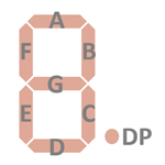 |
Display Fonts:
| Type | Calculator | Number Fonts | Decimal Separator |
Entry Overflow |
Calculating Overflow |
Minus | Seg. H Low V. |
| TMS0833NC | MBO Expert |
|

 The
TMS0833NC implements a so-called Timeout feature. When no key presses are detected
for about 20 seconds, the display blanks out and shows only a '-' in the
leftmost digit to reduce power consumption of the calculator. Timeout is
recoverable with an optional [D] key connected between the WDK Output and either
the KN or KO Inputs, or pressing any key assigned to the keyboard scan matrix
D8, D9/KN, KO, KP. We captured with a Digilent Digital Discovery Logic Analyzer
connected to a TMS0833NC and operated in the DCM-50A Platform, the transition
between normal operation and Timeout, before returning with pressing the [C] key
back to normal operation. The TMS0833NC actually "remembered" the previous
content of the display before clearing it due to the [C] key, the optional [D]
key would have preserved the previous calculation.
The
TMS0833NC implements a so-called Timeout feature. When no key presses are detected
for about 20 seconds, the display blanks out and shows only a '-' in the
leftmost digit to reduce power consumption of the calculator. Timeout is
recoverable with an optional [D] key connected between the WDK Output and either
the KN or KO Inputs, or pressing any key assigned to the keyboard scan matrix
D8, D9/KN, KO, KP. We captured with a Digilent Digital Discovery Logic Analyzer
connected to a TMS0833NC and operated in the DCM-50A Platform, the transition
between normal operation and Timeout, before returning with pressing the [C] key
back to normal operation. The TMS0833NC actually "remembered" the previous
content of the display before clearing it due to the [C] key, the optional [D]
key would have preserved the previous calculation.

 Scanning: Display and keyboard scanning is performed in D9 → D1 direction at a rate of about
370 Hz with the Digits and Segments blanked at State S1 and State S11:
Scanning: Display and keyboard scanning is performed in D9 → D1 direction at a rate of about
370 Hz with the Digits and Segments blanked at State S1 and State S11:
|
• State Time = 4 Clocks = 0.025 ms @ CK=160 kHz • Digit Time = 11 States (1 Instruction Cycle) = 0.275 ms @ CK=160 kHz • Scan Time = 10 Digit Times (D1 to D10 with D10 a dead cycle) = 2.75 ms @ CK=160 kHz |
If you have additions to the above article please email: joerg@datamath.org.
© Joerg Woerner, August 25, 2024. No reprints without written permission.