DATAMATH CALCULATOR MUSEUM
|
DATAMATH CALCULATOR MUSEUM |
Sharp Electronics Corporation introduced already in October 1969 with the QT-8D its first electronic calculator using five Large-Scale-Integration (LSI) Circuits manufactured by Rockwell Electronics before stating around 1971 to develop their own calculator chips. After various multi-chip designs, the LI2002 was Sharp's first commercial available single-chip calculator circuit and directly competing with other offerings from mostly American companies, namely Cal-Tex, General Instrument, Mostek, National Semiconductor, Rockwell and Western Digital.
The LI2002 was developed with a clear focus on battery operated handheld calculators using 8-digit or 9-digit Vacuum Fluorescent Displays (VFDs) with a very similar feature set to Texas Instruments' TMS0850 Product Family:
|
• Output drivers for low-voltage VFD up to 35 Volts • Integrated Clock Oscillator • Four Functions and Percent calculations • Floating point operation • Leading zero suppression • Automatic Constant on Multiplication and Division • 8-digit or 9-digit displays |
 Looking closely into
the LI2002 reveals a unique design approach tracing back to the earliest
electronic calculators, its complete logic is realized as a "hard-wired"
Register Processor
instead using the more common approach with a programmable ROM (Read-Only
Memory) to define the calculating algorithm. In 1965, before designers of
electronic desktop calculators could use Integrated Circuits (ICs), a
typical design used around discrete 3,000 transistors and diodes. In 1969 it
was commercially possible to integrate about 1,000 transistors in a
p-Channel MOS (PMOS) process on a silicon die measuring about 0.2" x 0.2" (5
mm x 5 mm) and having about 28 to 48 electrical connections to the outside
world, typical calculators like Sharp's QT-8D split the calculator
electronics into 4 to 6 "Multi-Chip Slices". Gordon E.
Moore - co-founder of Intel - postulated already in the 1960s that the number of
transistors that can be packed into a given unit of space will double about
every two years, paving the way for "single-chip calculator circuits" like
the TMS0100 introduced in September 1971 and
integrating around 5,500 transistors on its silicon die.
Looking closely into
the LI2002 reveals a unique design approach tracing back to the earliest
electronic calculators, its complete logic is realized as a "hard-wired"
Register Processor
instead using the more common approach with a programmable ROM (Read-Only
Memory) to define the calculating algorithm. In 1965, before designers of
electronic desktop calculators could use Integrated Circuits (ICs), a
typical design used around discrete 3,000 transistors and diodes. In 1969 it
was commercially possible to integrate about 1,000 transistors in a
p-Channel MOS (PMOS) process on a silicon die measuring about 0.2" x 0.2" (5
mm x 5 mm) and having about 28 to 48 electrical connections to the outside
world, typical calculators like Sharp's QT-8D split the calculator
electronics into 4 to 6 "Multi-Chip Slices". Gordon E.
Moore - co-founder of Intel - postulated already in the 1960s that the number of
transistors that can be packed into a given unit of space will double about
every two years, paving the way for "single-chip calculator circuits" like
the TMS0100 introduced in September 1971 and
integrating around 5,500 transistors on its silicon die.
Sharp was obviously
very experienced with hard-wired calculator logic, but its chip
manufacturing processes were rather conservative, our reverse-engineering
efforts of the LI2002 revealed a 12 um metal gate PMOS process. It was in
the early 1970s well understood, that the practical size limit of a consumer
grade PMOS chip is around 0.2" x 0.2" (5 mm x 5 mm) for an acceptable
production yield, allowing the integration of around 3,500 transistors with
a 12 um metal gate PMOS process - not sufficient for a ROM-based design.
Learn more about Hardware Architecture
of Electronic Calculators.
The lifecycle of the LI2002 was rather short, Sharp introduced within a few months improved products like the LI2003 and LI2006.
QUICK-LINK to Sharp Calculator Integrated Circuits.
| Type | Calculators | Keyboard | Constant (M-D-A-S) |
Digits | Fixed DP | Rounding | Special Functions |
Seg./Dig. Blanking |
(6,7,9) Font |
Entry Overflow |
Calculating Overflow |
| LI2002 | Lloyd's Accumatic 30, Silver-Reed SR80 | [+][−][=] | 1-2-X-X | 8 | Float | None | [%] | LB, TB NONE |
| Description | Comments | |
| Architecture | Single-chip Calculator | First Generation |
| Category | Register Processor | Hard-wired |
| Related | ||
| ROM Size | n.a. | n.a. |
| RAM Size | 108 Bits | 3 Registers * 36 Bits (9 Digits) |
| Outputs | 9 Digits 8 Segments |
VFD Digit Drivers VFD Segment Drivers |
| Inputs | 2 Keyboard 2 Clear |
Digit to Keyboard Scan-Matrix Active High, Active Low |
Capacity: Up to 8 digits (positive and negative)
Logic: Algebraic Chain Logic with Automatic Constant
[2] [x] [3] [+] [4] [x] [5] [=] → '50.'
Number Entry: Right-justified number entry, entering a ninth digit is ignored
[1] [2] [3] [4] [5] [6] [7] [8] [9] → '12345678.'
Decimal Point: First entered decimal point is used, additional decimal point entries are ignored
[1] [.] [2] [.] [3] → '1.23'
Fixed Decimal Point: Fixed decimal point arithmetic is not supported
Decimal Alignment: Decimal alignment is supported for additions and subtractions
[0] [.] [4] [5] [+] [0] [.] [5] [5] [=] → '1.00'
Clear: Automatic power-up clear implemented. [C] key clears the whole calculator, [CE] key clears last entry of a number
[1] [+] [2] [C] [3] [=] → '3.'; [1] [+] [2] [CE] [3] [=] → '4.'
Change Sign: Not supported. When performing multiplication or division, a negative value can only be assigned to the first number by pressing the [−] key before entering the number
[−] [2] [x] [3] [=] → '6.-'; [−] [2] [x] [−] [3] [=] → '5.-'
Number Display: Right-justified number display with leading-zero suppression
Negative Numbers: Negative numbers are shown with '-' immediate to the right of the number
Calculating Overflow: An overflow results in displaying a zero with all decimal points lit and is only recoverable using the [C] key
[1] [2] [3] [4] [5] [x] [1] [2] [3] [4] [5] [=] → '. . . . . . .0. .'
Divide By Zero: A division of a positive or negative number by zero results in displaying a zero with all decimal points lit and is only recoverable using the [C] key
[1] [:] [0] [=] → '. . . . . . .0. .'; [−] [1] [:] [0] [=] → '. . . . . . .0. .'
Timeout: Not supported
Rounding: Rounding of displayed calculating results is not supported
[2] [0] [:] [3] [=] → '6.6666666'
Automatic Constant: Implemented for multiplication (1st number used as constant) and division (2nd) with unusual behavior during division
[3] [x] [2] [=] [=] → '18.', [1] [=] → '3.'; [4] [x] [=] → '16.'; [4] [x] [=] [=] → '64.'
[3] [:] [2] [=] [=] → '0.75', [1] [=] → '0.5.'; [4] [:] [=] → '0.25; [4] [:] [=] [=] → '0.0625'
[3] [+] [2] [=] [=] → '5.', [1] [=] → '1.'; [4] [+] [=] [=] → '4.'
[3] [−] [2] [=] [=] → '1.', [1] [=] → '1.'; [4] [−] [=] [=] → '4.'
Reciprocal Function: The reciprocal function is implemented using the [:] key directly followed by the [=] key
[4] [:] [=] → '0.25'
Percent Function: The [%] key following the [x] key allows with the [+] and [−] keys mark-up and discount calculations
[2] [0] [x] [5] [%] → '1.', [=] → '20.'
[2] [0] [x] [5] [%] → '1.', [+] [=] → '21.'
[2] [0] [x] [5] [%] → '1.', [−] [=] → '19.'
Known Calculator Logic Bugs:
Negative Zero Bug: Certain calculations result in displaying a negative zero
[1] [−] [2] [+] [1] [=] → '0.-'; [−] [0] [.] [0] [0] [0] [1] [:] [1] [0] [0] [=] [=] → '0.-'
| Item | Min | Typ | Max | Unit | Comments |
| VSS | 0 | V | |||
| VDD | -8.0 | V | |||
| VGG | -16.0 | V | |||
| IDD | 2.3 | mA | REXT = 100 kOhm, Segment- and | ||
| IGG | 1.7 | mA | Digit-Driver Load 100 kOhm to VGG | ||
| VOUT | -35 | -30 | 0.3 | V | VFD Output Voltage through 100 kOhm Resistors |
| VIN (KN, KF) | VGG | 0.3 | V | Input Voltage through 100 kOhm Resistors | |
| Int. CK | 80 | kHz | REXT = 100 kOhm to VGG |
CLOCK GENERATOR
The LI2002 single-chip calculator circuit includes an internal oscillator providing non-overlapping two-phase clock signals CK1 and CK2 with a nominal frequency of 80 kHz. The oscillator is enabled by pulling Pin 3 (REXT) with a resistor REXT to VGG and is provided output signal levels between VSS and VGG. Instead of using a high-frequency oscillator and generating the two clock signal outputs CK1 and CK2 with counters and decoders, utilizes the LI2002 an RC-Oscillator and derives the clock signals from its on/off timing, generating a very unsymmetrical output-phase relation ship. We measured on our Device-under-Test (DUT) an active-low pulse of 3.5 us for CK1 and 4.5 us for CK2, with a gap of only 1 us between CK1 and CK2.
The frequency of the internal clock oscillator is set with the external resistor REXT, its nominal value is 100 kOhm for a typical frequency of 80 kHz. We observed values of 100 kOhm and 120 kOhm used on the printed circuit boards (PCBs) of various calculator based on LI2002 devices. Here at the Datamath Calculator Museum we operate the LI2002 DUT with an external 100 kOhm resistor but verify its operation between 50 kOhm and 150 kOhm.
The operating frequency of the internal clock oscillator depends not only on the external resistor, but its supply voltages VDD and VGG, too. We observed with our DUT a positive gradient of the oscillation frequency while varying VDD and VGG simultaneously.
AUTO CLEAR
The LI2002 is providing two input pins labeled ATC and /ATC to initialize its internal registers after power-up or error conditions. In most known applications the /ATC pin is pulled-up with a resistor of 220k Ohm to VSS and connected with a 50nF capacitor to VGG, forming a time constant of around 10 ms to reset the LI2002 after applying power. The [C] key is connected parallel to the capacitor. The ATC input pin is typically pulled-down with a resistor to VDD.
INTER-DIGIT SEGMENT BLANKING
The LI2002 is blanking its Segment Outputs briefly before and after the Digit Output change, while scanning the keyboard and display.
8-DIGIT DISPLAYS
The LI2002 is using the Digit Time D1 only to output the Minus sign '-' for negative numbers, all error conditions are displayed with an "8-Digit friendly" zero with all decimal points lit '. . . . . . .0. .'. This allows to use a single LED connected to the corresponding Segment Output G and driver with a transistor connected to Digit Output D1 as Minus "dot", instead a 9th digit.
The Datamath Calculator Museum DCM-50A (PLAYGROUND) supports the Characterization of the LI2002 single-chip calculator circuit using the DCM-50A Playground DIL42 Adapter mounted on top of the DCM-50A PG Frame Carrier and the voltages VSS set to 8.0V and VDD/VGG set to -8.0V. Alternatively, the more flexible - but less comfortable - DCM-50A Playground BB400 Adapter can be used.
The LI2002 was manufactured in a 12 um metal gate PMOS process (metal width = 0.45 mil / 12 um, metal spacing = 0.45 mil / 12 um, diffusion width = 0.45 mil / 12 um, diffusion spacing = 0.45 mil / 12 um).
The die size of the LI2002 is approximately 190 mils * 205 mils / 4.8 mm * 5.2 mm.
The LI2002 uses a standard 0.6” wide 28-pin DIP (Dual In-line Package with a 0.1” / 2.54 mm lead pitch). Three different styles of Ceramic Packages are known as of today.
|
• VSS/VDD/VGG - Confirmed Pin Function from Die Photo • (VSS/VDD/VGG) - Pin Function from Calculator Schematics • N.C. - Confirmed Pin Function from Die Photo or Pin Measurement • (N.C.) - Pin Function from Calculator Schematics |
| Pin | IO | Function | Pin | IO | Function |
| 1 | O | Clock Output 2 | 28 | O | Digit driver D1 (sign) |
| 2 | O | Clock Output 1 | 27 | O | Digit driver D2 (LSD) |
| 3 | I | REXT | 26 | O | Digit driver 3 |
| 4 | V | Negative Voltage VGG | 25 | O | Digit driver 4 |
| 5 | V | Negative Voltage VDD | 24 | O | Digit driver 5 |
| 6 | O | Segment driver G | 23 | O | Digit driver 6 |
| 7 | O | Segment driver F | 22 | O | Digit driver 7 |
| 8 | O | Segment driver E | 21 | O | Digit driver 8 |
| 9 | O | Segment driver D | 20 | O | Digit driver 9 (MSD) |
| 10 | O | Segment driver C | 19 | I | Key-matrix input F |
| 11 | O | Segment driver B | 18 | I | Key-matrix input N |
| 12 | O | Segment driver A | 17 | not connected | |
| 13 | O | Segment driver DP | 16 | I | Automatic Clear (low) |
| 14 | V | Common Voltage VSS | 15 | I | Automatic Clear (high) |
| The Segment drivers A-G and DP (Decimal Point) are connected to the display in the pictured way. | 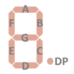 |
The keyboards of all calculators based on the LI2002 consist of an x/y-matrix connected to nine digit-driver outputs D1 to D9 and the key-matrix inputs KN (Numbers) and KF (Functions). The [C] key is connected to the dedicated ATC or /ATC input.
Scanning is performed in D1 → D9 direction at a rate of about 2,200 Hz:
|
• State Time = 1 Clock =
0.0125 ms @ CK1, CK2=80 kHz • Digit Time = 4 States = 0.05 ms @ CK1, CK2=80 kHz • Scan Time = 9 Digit Times = 0.45 ms @ CK1, CK2=80 kHz |
LI2002 | |||
| KN | KF | /ATC | |
| VGG | C | ||
| D1 | 2 | % | |
| D2 | 3 | = | |
| D3 | 4 | + | |
| D4 | 5 | − | |
| D5 | 6 | × | |
| D6 | 7 | ÷ | |
| D7 | 8 | . | |
| D8 | 9 | 0 | |
| D9 | 1 | CE | |
Calculators based on the LI2002 typically make use of 8-digit or 9-digit low-voltage VFDs (Vacuum Fluorescent Displays).
If you have additions to the above datasheet please email: joerg@datamath.org.
© Joerg Woerner, September 29, 2024. No reprints
without written permission.
