DATAMATH CALCULATOR MUSEUM
|
|
DATAMATH CALCULATOR MUSEUM |
Characterization of NEC Single-chip Calculator Circuits - µPD273
The DCM-50A Platform supports the Characterization of many Non-TI single-chip calculator circuits with up to 42-pin packages using the DCM-50A Playground DIL42 Adapter mounted on top of the DCM-50A PG Frame Carrier with the voltages VSS and VDD/VGG set to the appropriate levels.

![]() Device-under-Test:
Device-under-Test:
| • Package Markings Top:
µPD273C K3Y106 • Package Markings Bottom: • Donor Calculator: Brother PROCAL 408AY, January 1974 |
Keyboard: The Brother PROCAL 408AY makes use of a keyboard with 19 plastic keys pushing small conductive carbon discs mounted in two large silicone rubber membranes against contacts etched on the Main-PCB and using a highly conductive plating. The sliding switch for Power On/Off and the Constant function of the calculator is wired to the Main-PCB. All switches are arranged in a 10*2 matrix with the rows connected to the D1-D10 Outputs (Digit Scan) and the columns connected to the NK and KF Inputs (Keyboard Scan) of the µPD273 single-chip calculator circuit. The [C] key is connected directly between common voltage VSS and the CL input of the µPD273.
Keyboard Matrix of the Brother PROCAL 408AY:
µPD273 | ||||
| NK | FK | CL | ||
| VSS | C | |||
| D1 | 1 | |||
| D2 | 3 | CI | ||
| D3 | 2 | . | ||
| D4 | 6 | × | ||
| D5 | 7 | ÷ | ||
| D6 | 5 | − | ||
| D7 | 4 | + | ||
| D8 | 0 | [ - K] | ||
| D9 | 8 | = | ||
| D10 | 9 | % | ||
![]() Display:
The Brother PROCAL 408AY makes use of an 9-digit ISE Electronics DP90A low-voltage
Vacuum Fluorescent Display (VFD) connected directly to the respective 9 Digit
Outputs D1 to D8 and D10 and 8 Segment Outputs SA to SG and SDP of the µPD273 and biased to approximately -25 Volts.
Segment Output SH of the µPD273 to display the Fancy-Four is not used.
Display:
The Brother PROCAL 408AY makes use of an 9-digit ISE Electronics DP90A low-voltage
Vacuum Fluorescent Display (VFD) connected directly to the respective 9 Digit
Outputs D1 to D8 and D10 and 8 Segment Outputs SA to SG and SDP of the µPD273 and biased to approximately -25 Volts.
Segment Output SH of the µPD273 to display the Fancy-Four is not used.
Display Layout:
| ISE DP90A |
|
|
| The Segment drivers A-G and DP (Decimal Point) are connected to the ISE DP90A display in the pictured way. Segment driver H is not connected to the display. | 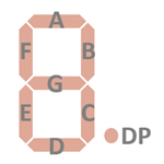 |
Display Fonts:
| Type | Calculator | Number Fonts | Decimal Separator |
Thousands Separator |
Entry Overflow |
Calculating Overflow |
Minus |
| µPD273 | Brother PROCAL 408AY |
n.a. |

 Scanning: Display
and keyboard scanning is performed in D1 → D10 direction at a rate of about
1,000 Hz:
Scanning: Display
and keyboard scanning is performed in D1 → D10 direction at a rate of about
1,000 Hz:
|
• State Time = 1 Clock =
0.025 ms @ CK=40 kHz • Digit Time = 4 States = 0.100 ms @ CK=40 kHz • Scan Time = 10 Digit Times (D1 to D10) = 1.000 ms @ CK=40 kHz |

![]() Device-under-Test:
Device-under-Test:
| • Package Markings Top:
µPD274C H4X016 • Package Markings Bottom: • Donor Calculator: Prinztronic Asset, January 1975 |
Keyboard: The Prinztronic Asset makes use of a keyboard assembly with 19 individual spring loaded long-stroke plastic keys pushing small conductive carbon discs against against gold plated contacts etched on a single-sided phenolic printed circuit board (PCB). The sliding switch for Power On/Off is using a small stamped metal part pressing against two contacts on the PCB while the Constant function of the calculator is hard-wired on the PCB, using a diode placed on the Main-PCB of the calculator. All switches are arranged in a 10*2 matrix with the rows connected to the D1-D10 Outputs (Digit Scan) and the columns connected to the NK and KF Inputs (Keyboard Scan) of the µPD274 single-chip calculator circuit. The [C] key is connected directly between common voltage VSS and the CL input of the µPD274.
Keyboard Matrix of the Prinztronic ASSET:
µPD274 | ||||
| NK | FK | CL | ||
| VSS | C | |||
| D1 | 1 | |||
| D2 | 3 | CE | ||
| D3 | 2 | . | ||
| D4 | 6 | × | ||
| D5 | 7 | ÷ | ||
| D6 | 5 | − | ||
| D7 | 4 | + | ||
| D8 | 0 | [Diode] | ||
| D9 | 8 | = | ||
| D10 | 9 | % | ||
![]() Display:
The Prinztronic Asset makes use makes use of an 9-digit Itron DP95A low-voltage
Vacuum Fluorescent Display (VFD) connected directly to the respective 9 Digit
Outputs D1 to D8 and D10 and 8 Segment Outputs SA to SG and SDP of the µPD274 and biased to approximately -25 Volts.
Segment Output SH of the µPD274 to display the Fancy-Four is not used.
Display:
The Prinztronic Asset makes use makes use of an 9-digit Itron DP95A low-voltage
Vacuum Fluorescent Display (VFD) connected directly to the respective 9 Digit
Outputs D1 to D8 and D10 and 8 Segment Outputs SA to SG and SDP of the µPD274 and biased to approximately -25 Volts.
Segment Output SH of the µPD274 to display the Fancy-Four is not used.
Display Layout:
| Itron DP95A |
|
|
| The Segment drivers A-G and DP (Decimal Point) are connected to the Itron DP95A display in the pictured way. Segment driver H is not connected to the display. | |
Display Fonts:
| Type | Calculator | Number Fonts | Decimal Separator |
Thousands Separator |
Entry Overflow |
Calculating Overflow |
Minus |
| µPD274 | Prinztronic Asset |
n.a. |

 Scanning: Display
and keyboard scanning is performed in D1 → D10 direction at a rate of about
1,000 Hz:
Scanning: Display
and keyboard scanning is performed in D1 → D10 direction at a rate of about
1,000 Hz:
|
• State Time = 1 Clock =
0.025 ms @ CK=40 kHz • Digit Time = 4 States = 0.100 ms @ CK=40 kHz • Scan Time = 10 Digit Times (D1 to D10) = 1.000 ms @ CK=40 kHz |

![]() Device-under-Test:
Device-under-Test:
| • Package Markings Top:
µPD275C H49066 • Package Markings Bottom: • Donor Calculator: Triumph-Adler 80C (Model EC21), November 1974 |
Keyboard: The Triumph-Adler 80C (EC21) makes use of a keyboard assembly with a sliding power switch and 19 spring-supported plastic keys pushing small fingers on stamped sheet-metal pieces against contacts etched on a single-sided phenolic PCB. The sliding switches for Power On/Off and the Constant function are using small stamped metal parts pressing against two contacts on the PCB . All switches are arranged in a 10*2 matrix with the rows connected to the D1-D10 Outputs (Digit Scan) and the columns connected to the NK and KF Inputs (Keyboard Scan) of the µPD275 single-chip calculator circuit. The [C] key is connected directly between common voltage VSS and the CL input of the µPD275.
Keyboard Matrix of the Triumph-Adler 80C (EC21):
µPD275 | ||||
| NK | FK | CL | ||
| VSS | C | |||
| D1 | 1 | |||
| D2 | 3 | CI | ||
| D3 | 2 | . | ||
| D4 | 6 | × | ||
| D5 | 7 | ÷ | ||
| D6 | 5 | − | ||
| D7 | 4 | +/= | ||
| D8 | 0 | [ - K] | ||
| D9 | 8 | |||
| D10 | 9 | % | ||
![]() Display:
The Triumph-Adler 80C (EC21) makes use makes use of an 9-digit Futaba 9-ST-12 low-voltage
Vacuum Fluorescent Display (VFD) connected directly to the respective 9 Digit
Outputs D1 to D8 and D10 and 8 Segment Outputs SA to SG and SDP of the µPD275 and biased to approximately -25 Volts.
Segment Output SH of the µPD275 to display the Fancy-Four is not used.
Display:
The Triumph-Adler 80C (EC21) makes use makes use of an 9-digit Futaba 9-ST-12 low-voltage
Vacuum Fluorescent Display (VFD) connected directly to the respective 9 Digit
Outputs D1 to D8 and D10 and 8 Segment Outputs SA to SG and SDP of the µPD275 and biased to approximately -25 Volts.
Segment Output SH of the µPD275 to display the Fancy-Four is not used.
Display Layout:
| Futaba 9-ST-12 |
|
|
| The Segment drivers A-G and DP (Decimal Point) are connected to the Futaba 9-ST-12 display in the pictured way. Segment driver H is not connected to the display. | |
Display Fonts:
| Type | Calculator | Number Fonts | Decimal Separator |
Thousands Separator |
Entry Overflow |
Calculating Overflow |
Minus |
| µPD275 | Triumph-Adler 80C (EC21) |
n.a. |

 Scanning: Display
and keyboard scanning is performed in D1 → D10 direction at a rate of about
1,000 Hz:
Scanning: Display
and keyboard scanning is performed in D1 → D10 direction at a rate of about
1,000 Hz:
|
• State Time = 1 Clock =
0.025 ms @ CK=40 kHz • Digit Time = 4 States = 0.100 ms @ CK=40 kHz • Scan Time = 10 Digit Times (D1 to D10) = 1.000 ms @ CK=40 kHz |
If you have additions to the above article please email: joerg@datamath.org.
© Joerg Woerner, April 16, 2025. No reprints without written permission.