DATAMATH CALCULATOR MUSEUM
|
DATAMATH CALCULATOR MUSEUM |
Commodore 885D
| Date of introduction: | 1974 | Display technology: | LED-stick |
| New price: | Display size: | 8 + Sign | |
| Size: | 5.7" x 3.0" x
0.9" 146 x 76 x 23 mm3 |
||
| Weight: | 3.7 ounces, 106 grams | Serial No: | 029851 |
| Batteries: | 9V | Date of manufacture: | mth 09 year 1974 |
| AC-Adapter: | no.505 or DC-620R | Origin of manufacture: | USA |
| Precision: | 8 | Integrated circuits: | TMS0807, DM75491, DM75492 |
| Logic: | Chain | Displays: | National Semiconductor NSA198 |
| Memories: | |||
| Program steps: | Courtesy of: | Joerg Woerner |

![]() This Commodore
Model 885D calculator introduced in 1974 is a perfect example how to reduce
manufacturing costs without sacrificing product quality too much. Like
Commodore's first handheld, battery operated calculator, the Commodore C110,
is the 885D centered around a calculator brain from Texas Instruments.
This Commodore
Model 885D calculator introduced in 1974 is a perfect example how to reduce
manufacturing costs without sacrificing product quality too much. Like
Commodore's first handheld, battery operated calculator, the Commodore C110,
is the 885D centered around a calculator brain from Texas Instruments.


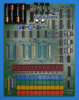
 Dismantling
the featured Commodore 885D calculator manufactured in September 1974 in the
United States is as easy as it can get, the two housing parts are just snapped
together. The only screws used in the calculator are holding its electronics
securely in place.
Dismantling
the featured Commodore 885D calculator manufactured in September 1974 in the
United States is as easy as it can get, the two housing parts are just snapped
together. The only screws used in the calculator are holding its electronics
securely in place.
 We started on our quest to
Record the ROM
Content of the TMS0807 single-chip calculator circuit deeper into the
internals of the featured Commodore 885D and made some surprising findings:
We started on our quest to
Record the ROM
Content of the TMS0807 single-chip calculator circuit deeper into the
internals of the featured Commodore 885D and made some surprising findings:
|
• The keyboard is integrated with the main
electronics onto a single printed circuit board (PCB) • The TMS0807 is operated with the same voltage for its VDD and rails VGG • The design uses to different display drivers |
![]() Calculating Unit: The TMS0807 is a member of the TMS0800 Product Family and tracing back to
the TMS1802NC, the first available standard calculator building block on a chip,
later renamed into TMS0102. The TMS0800
kept the size of the Instruction ROM (Read-Only Memory), but decreased the Data
Memory from 13 Digits Registers to 11 Digit Registers and added both integrated
segment drivers for the LED display and a clock generator.
Calculating Unit: The TMS0807 is a member of the TMS0800 Product Family and tracing back to
the TMS1802NC, the first available standard calculator building block on a chip,
later renamed into TMS0102. The TMS0800
kept the size of the Instruction ROM (Read-Only Memory), but decreased the Data
Memory from 13 Digits Registers to 11 Digit Registers and added both integrated
segment drivers for the LED display and a clock generator.
With low-cost battery operated LED calculators in mind, Texas Instruments added a so-called Timeout feature to the TMS0800 devices. When no key presses are detected for about 20 seconds, the display blanks out and shows only a '-' in the leftmost digit to reduce power consumption of the calculator. This Commodore 885D is one of the few known calculators using the Timeout feature.
![]() Display: This
Commodore 885D calculator manufactured
in September 1974 makes use of a National Semiconductor NS198 9-Digit display module with nine 7-Segment displays chips bonded onto a PCB and magnified with a clear plastic lens. The display module is connected with 17 pins to the Main-PCB
and follows the industry standard pinout sans the unused, leftmost pin.
Display: This
Commodore 885D calculator manufactured
in September 1974 makes use of a National Semiconductor NS198 9-Digit display module with nine 7-Segment displays chips bonded onto a PCB and magnified with a clear plastic lens. The display module is connected with 17 pins to the Main-PCB
and follows the industry standard pinout sans the unused, leftmost pin.

![]()
![]() Display Driver: The PCB of the disassembled
Commodore 885D uses with the DM75492 a 6-channel digit driver and interestingly
with the DM75491 a 4-channel segment driver. At first glance a big surprise, but
looking up the internal circuit diagrams of the two chips shows that they
utilize an almost identical design. Main difference between the two chips is the
connection of the Emitter of their output transistors, the DM75491 makes them
individually accessible while the DM75492 hardwires them to the GND pin. The PCB
of the featured Commodore 885D calculator shows the four pins to access the
Emitter of the DM75491 output transistors connected to the GND pin, hence
rendering the segment drivers to digit drivers. At a second look an interesting
approach but most likely were the DM75491 and DM75492 sourced in pairs, keep in
mind that the single-chip calculator circuits without integrated segment drivers
usually used two external segment drivers and two external digit drivers.
Display Driver: The PCB of the disassembled
Commodore 885D uses with the DM75492 a 6-channel digit driver and interestingly
with the DM75491 a 4-channel segment driver. At first glance a big surprise, but
looking up the internal circuit diagrams of the two chips shows that they
utilize an almost identical design. Main difference between the two chips is the
connection of the Emitter of their output transistors, the DM75491 makes them
individually accessible while the DM75492 hardwires them to the GND pin. The PCB
of the featured Commodore 885D calculator shows the four pins to access the
Emitter of the DM75491 output transistors connected to the GND pin, hence
rendering the segment drivers to digit drivers. At a second look an interesting
approach but most likely were the DM75491 and DM75492 sourced in pairs, keep in
mind that the single-chip calculator circuits without integrated segment drivers
usually used two external segment drivers and two external digit drivers.
Clock: The Commodore 885D makes use of the internal clock oscillator of the TMS0800 chip, we identified a resistor with 150k Ohm connected between Pin 14 (REXT//Clock Select) of the TMS0807 and the VDD / VGG power supply line, resulting in a clock frequency of about of 120 kHz.
Power Supply: The Commodore 885D is powered by a disposable 9 Volt battery and can be operated with an external, DC adapter, too. The PCB of the calculator hosts a power converter module to generate the VDD and VGG supply voltages for the TMS0807 chip. We observed with the featured calculator manufactured in September 1974 voltages of VDD and VGG = -16.4 V while operated with VBAT = 9.0 V. Looking into the layout artwork of the PCB we could indeed verify that the two power supply pins of the TMS0807 are connected together to the output of the power converter module. A rather unusual approach, the TMS0800 specifications define a typical value for VDD and VGG of -10.0 V and -15.8 V, respectively. With a minimum required voltage of -9.5 V for the TMS0800, using the 9 Volt battery directly for VDD was obviously not an option. Texas Instruments introduced later with the TMS0830 Product Family a variation of the TMS0800 designed for the direct use with 9 Volt batteries. The power consumption of the Commodore 885D is clearly on the higher end, mainly attributed to the 47 Ohm resistor connected between the digit drivers and the negative pin of the 9 battery, and resulting in a rather high current for the LED display:
| Mode | Display | Current VBAT = 3.0 V |
Clock Frequency |
| Timeout | - | 14 mA | 123 kHz |
| Calculating | 0. | 19 mA | 123 kHz |
| Calculating | 88888888. | 81 mA | 123 kHz |
Designing a handheld calculator using an LED display and a disposable 9 Volt battery might result in a cost effective design for the manufacturer, but it is not very efficient in its power budget and the user pays over the lifetime of the product a high price for batteries. The power consumption for the Commodore 885D results in about 170 mW displaying a '0.' and a whooping 730 mW with all segments but the minus sign illuminated. Due to the use of the Timeout feature of the TMS0800 chips, after about 20 seconds without user operation, the power consumption drops to about 120 mW while displaying a '-'. A similar MBO Expert calculator based on the later TMS0833 single-chip calculator circuit powered directly from the 9 Volt battery, showed slightly lower values with about 120 mW displaying a '0.' and about 500 mW with all segments but the minus sign illuminated. A Canon LE-84 calculator using four disposable 1.5 Volt Alkaline batteries and a DC/DC converter for its TMS0801 chip clocks in at around 100 mW and 320 mW, respectively. A fresh 9 Volt Alkaline battery would last around 10 to 30 hours in the Commodore 885D and MBO Expert calculators, while 4 AA-sized Alkaline batteries would power the Canon LE-84 up to 100 hours. At first glance might these numbers be astonishing, but they are easy to explain with Kirchhoff's second rule (the loop rule). In a closed loop, whatever energy is supplied by a voltage source, the energy must be transferred into other forms by the devices in the loop. Kirchhoff's loop rule states that the algebraic sum of all potential differences, including the voltage sources, in any loop must be zero.
With the numbers from the featured Commodore 885D, we calculate in a first step the average current per segment. The differences between the '0.' and '88888888.' displays are 50 segments and 62 mA, or 1.24 mA per segment. The TMS0807 chip is scanning the digits and segments with a 1:10 duty cycle, resulting in 12.4 mA average segment current per Digit Time. Each Digit Time has 11 State Times with S1 and S11 blanking the segments for a peak current of 15.0 mA per segment and around 105 mA per digit. The high-efficiency LED chips used with the calculator have a voltage drop of around 1.7 V at 15 mA segment current, and with a 9 Volt battery the sum of all other components in the loop will "burn" around 7.2 V:
| • TMS0807 segment driver (1.0 V) - LED chip (1.7 V) - DM75492/DM75491 digit driver (1.0 V) - 47 Ohm resistor (5.3 V) |
The Canon LE-84 calculator on the other hand is using four 1.5 Volt batteries in series for the LED driver circuitry and consequently needs to "burn" just around 4 V between power supply and LED chips. And the true master is Texas Instruments with its TI-2500-II design, using only two 1.5 Volt batteries and "burning" just 1 V between power supply and LED chips.
Keyboard: Looking at the Commodore 885D calculator, you might have already noticed its somehow odd design with a large keyplate but rather small keys and a huge gap between the upper row of the keys and the LED display. Well, aone of the results of lowering manufacturing costs of a calculator, the keyboard contacts are integrated with the main electronics on a single printed circuit board (PCB). The keys use small, flat springs that make contact with the gold-plated traces on the PCB and even the power switch uses the same idea.
 With
the DCM-50A Platform developed to
Characterize and
Reverse-engineer
Single-chip Calculator Circuits we could proof that the
Program Code of the
TMS0807 is tracing back to the
TMS0803 but dropped its Decimal
Alignment feature in lieu of the square root function. Other changes are the
implementation of the percent function and a different programming of the
segment decoder PLA.
With
the DCM-50A Platform developed to
Characterize and
Reverse-engineer
Single-chip Calculator Circuits we could proof that the
Program Code of the
TMS0807 is tracing back to the
TMS0803 but dropped its Decimal
Alignment feature in lieu of the square root function. Other changes are the
implementation of the percent function and a different programming of the
segment decoder PLA.
If you have additions to the above article please email: joerg@datamath.org.
© Joerg Woerner, August 29, 2024. No reprints without written permission.