DATAMATH CALCULATOR MUSEUM
|
DATAMATH CALCULATOR MUSEUM |
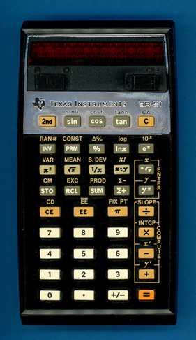
Texas Instruments SR-51 (Engineering Sample)
| Date of introduction: | January 1975 | Display technology: | LED modules + lens |
| New price: | $224.95 | Display size: | 10 + 2 |
| Size: | 5.8" x 3.2" x
1.3" 147 x 81 x 32 mm3 |
||
| Weight: | 8.5 ounces, 240 grams | Serial No: | 0000197 |
| Batteries: | BP1 | Date of manufacture: | wk 35 year 1974 |
| AC-Adapter: | AC9200 | Origin of manufacture: | USA |
| Precision: | 13 | Integrated circuits: | TMC0501, TMC0522, TMC0523 |
| Logic: | Sum-of-Products | Displays: | |
| Memories: | 3 | ||
| Program steps: | Courtesy of: | Joerg Woerner | |
| Download manuals: | |
![]()
![]() When
we received this SR-51 (Engineering Sample) from a former Texas Instruments
employee, it still included a form TI-22057 called "Employee Calculator Sales". Four
details on this sales receipt caught our attention:
When
we received this SR-51 (Engineering Sample) from a former Texas Instruments
employee, it still included a form TI-22057 called "Employee Calculator Sales". Four
details on this sales receipt caught our attention:
|
• The calculator model is
listed as SR-51E, probably a reference to Engineering Sample • The serial number contains only three digits instead the usual four or five digits • The sales price was with US $165.90 rather high, the SRP of the SR-51 was US $224.95 • The sales took place in March 1975, two months after the formal introduction of the SR-51 |
We know from internal Texas Instruments documentation that the later SR-56 Programmable was internally called SR-51P, suggesting a close relationship to this SR-51. And maybe there was this SR-51E and E was for Engineering while P was for Programmable? Just a thought with respect to the various changes between the original SR-50 and this SR-51 (Engineering Sample).
The 3-digit serial number clearly indicates that the featured calculator was not meant for Sales, we learned from TI's very first electronic calculator, the famous TI-2500 Datamath, that the first Pre-Series models in the white housing used serial numbers D0000-00xxx, the next Pre-Series models in the tan housing used D0000-0xxxx and the final production used D0000-xxxxx before switching to 2500-xxxxx. Here at the Datamath Calculator Museum we host for both the SR-52 and SR-56 a database with the known serial numbers, it does not include a single 3-digit serial number as of today.
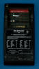
 Dismantling the featured SR-51E (Engineering Sample)
Scientific calculator assembled in August 1974 in
Dallas, Texas reveals a perfectly engineered design looking very similar to the
SR-50 introduced on January 15th, 1974. The internal construction of
the SR-51E is based on a sandwich of two
printed circuit boards (PCBs) separated with a plastic frame holding the
electric contacts for the rechargeable BP1
Battery Pack using three AA-sized NiCd cells and mounting hardware for the PCBs
and the bottom shell of the housing.
Dismantling the featured SR-51E (Engineering Sample)
Scientific calculator assembled in August 1974 in
Dallas, Texas reveals a perfectly engineered design looking very similar to the
SR-50 introduced on January 15th, 1974. The internal construction of
the SR-51E is based on a sandwich of two
printed circuit boards (PCBs) separated with a plastic frame holding the
electric contacts for the rechargeable BP1
Battery Pack using three AA-sized NiCd cells and mounting hardware for the PCBs
and the bottom shell of the housing.
![]()
![]()
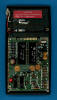
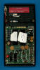 At
first glance the smaller of the two PCBs
seems to use the same "Calculator Brain" setup as the SR-50 but a
closer looks shows two TMC0522 and
TMC0523 Scanning and Read-Only Memory
Chips mounted on top of each other in a piggy-back manner next to
the
TMC0501 Arithmetic Chip instead the
SR-50's single
TMC0521 Chip. Other apparent changes are
the gold-plated contacts for the PC-100 Printer Cradle
(which is officially not supported by the SR-51) and a very complex circuitry
for the clock signal generation of the calculator. The three calculator chips
and a potentially connected PC-100 are using two non-overlapping clock signals
PHI 1 and PHI 2 with a frequency of up to 250 kHz. On the PCB of the original
SR-50 we located a fully transistorized clock circuitry that slows down the
clock frequency of the calculator to optimize the power budget while the
calculator is just displaying results and scanning the keyboard and not
performing actual calculations.
At
first glance the smaller of the two PCBs
seems to use the same "Calculator Brain" setup as the SR-50 but a
closer looks shows two TMC0522 and
TMC0523 Scanning and Read-Only Memory
Chips mounted on top of each other in a piggy-back manner next to
the
TMC0501 Arithmetic Chip instead the
SR-50's single
TMC0521 Chip. Other apparent changes are
the gold-plated contacts for the PC-100 Printer Cradle
(which is officially not supported by the SR-51) and a very complex circuitry
for the clock signal generation of the calculator. The three calculator chips
and a potentially connected PC-100 are using two non-overlapping clock signals
PHI 1 and PHI 2 with a frequency of up to 250 kHz. On the PCB of the original
SR-50 we located a fully transistorized clock circuitry that slows down the
clock frequency of the calculator to optimize the power budget while the
calculator is just displaying results and scanning the keyboard and not
performing actual calculations.
![]()
![]() This feature is gone with the SR-51 and we
noticed a complex arrangement of two transistors as free-running oscillator, a
SN74LS74 D-Type Flip Flop dividing the signal by two and four SN74LS02 2-Input
NOR Gates generating the control signals of two level-shifters composed of four
transistors to generate PHI 1 and PHI 2. Looks at first glance like an overkill
but supports together with the Printer Cradle contacts the idea that Texas
Instruments was already actively working on the SR-51P, better known as SR-56
Programmable. From an engineering point of view the design requirements for the
clock signal generation of a standalone SR-50 and an SR-51 mounted on a PC-100
Printer Cradle are completely different. The distance between the clock
generator and the two TMC0501 and TMC0521 Chips used in the SR-50 is about 50 mm
(2"), while the SR-51 generates a load of three chips within the SR-51 and
another three chips inside the PC-100, separated by a connector, flexible cable
and PCB traces by more than 100 mm (4"). And we know that the SR-51 "somehow"
works on the PC-100A,
which uses the same firmware as the PC-100. Learn more about
Printing with the SR-51 / SR-51A.
This feature is gone with the SR-51 and we
noticed a complex arrangement of two transistors as free-running oscillator, a
SN74LS74 D-Type Flip Flop dividing the signal by two and four SN74LS02 2-Input
NOR Gates generating the control signals of two level-shifters composed of four
transistors to generate PHI 1 and PHI 2. Looks at first glance like an overkill
but supports together with the Printer Cradle contacts the idea that Texas
Instruments was already actively working on the SR-51P, better known as SR-56
Programmable. From an engineering point of view the design requirements for the
clock signal generation of a standalone SR-50 and an SR-51 mounted on a PC-100
Printer Cradle are completely different. The distance between the clock
generator and the two TMC0501 and TMC0521 Chips used in the SR-50 is about 50 mm
(2"), while the SR-51 generates a load of three chips within the SR-51 and
another three chips inside the PC-100, separated by a connector, flexible cable
and PCB traces by more than 100 mm (4"). And we know that the SR-51 "somehow"
works on the PC-100A,
which uses the same firmware as the PC-100. Learn more about
Printing with the SR-51 / SR-51A.
We are confident that the SR-51 was meant to be operated on the PC-100 Printer Cradle but delays in the development of the PC-100 shifted priorities. When Texas Instruments introduced with the SR-50 the TMS0500 Building Blocks for Scientific and Programmable Calculators, they opted for a chronological order of their part-numbering scheme. Looking into the TMC0520 Scanning and Read-Only Memory Chips and the TMC0560 Bare Read-Only Memory Chips, it is obvious that the PC-100 was developed before the SR-52:
|
• TMC0521 - SR-50 (January 1974) • TMC0522/523 - SR-51 (January 1975) • TMC0524 - SR-52 (September 1975) • TMC0526 - SR-60 (1976) • (TMC0527/528) - SR-56 (May 1976) |
|
• TMC0561 - PC-100 (September 1975) • TMC0562/563 - SR-52 (September 1975) • TMC0564-568 - SR-60 (1976) • TMC0569 - PC-100 (September 1975) • TMC0570 - SR-60 (Replaces TMC0568) • TMC0571 - TI-59 (May 1977) |
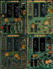 Comparing
the Main-PCBs of four different evolutions of the SR-51
Scientific Calculator manufactured between August 1974 and May 1975, one month
before its discontinuation, shows only subtle differences in the layout but
holding a big surprise! The early three Main-PCBs have Pin 5 of the Print Cradle
connector floating while the SR-51 from the last production month has Pin 5
wired to Pin 14 of the TMC0523 SCOM, its D0 Digit Time output. Looking into the
circuit diagrams of both the SR-52 Programmable Calculator and the PC-100 Print
Cradle we understand that a connection between D0 and the keymatrix input KP of
the TMC0501 is used to detect PC-100. Or in other words: Texas Instruments
consciously removed in the first iterations of the Main-PCB design the
capability of the SR-51 Firmware to detect a possibly connected PC-100 -
explaining why some SR-51 had success with printing and others not. The magic of
a simple blue wire...
Comparing
the Main-PCBs of four different evolutions of the SR-51
Scientific Calculator manufactured between August 1974 and May 1975, one month
before its discontinuation, shows only subtle differences in the layout but
holding a big surprise! The early three Main-PCBs have Pin 5 of the Print Cradle
connector floating while the SR-51 from the last production month has Pin 5
wired to Pin 14 of the TMC0523 SCOM, its D0 Digit Time output. Looking into the
circuit diagrams of both the SR-52 Programmable Calculator and the PC-100 Print
Cradle we understand that a connection between D0 and the keymatrix input KP of
the TMC0501 is used to detect PC-100. Or in other words: Texas Instruments
consciously removed in the first iterations of the Main-PCB design the
capability of the SR-51 Firmware to detect a possibly connected PC-100 -
explaining why some SR-51 had success with printing and others not. The magic of
a simple blue wire...
 With the BP1 battery pack having a nominal voltage of
around 3.7 Volts but the calculator chips manufactured in a 8 um metal gate PMOS
process requiring two voltages of -10.0 Volts and -15.8 Volts, does the SR-51
include a transformer based DC/DC converter designed with discrete components.
With the BP1 battery pack having a nominal voltage of
around 3.7 Volts but the calculator chips manufactured in a 8 um metal gate PMOS
process requiring two voltages of -10.0 Volts and -15.8 Volts, does the SR-51
include a transformer based DC/DC converter designed with discrete components.
![]()
![]()
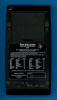
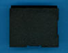
 The larger of the two PCBs contains the display of the
calculator composed of 14 discrete 7-Segment LED modules with an attached
magnifier lens and two SN27882 display drivers but most of the real estate is dedicated
to the 40 snap action switches of the keyboard. Tracing back to the reliable Klixon™
switches and using double shot injection molding keys, the SR-51 might be
together with the SR-50 TI's
most reliable calculators ever produced. Time will tell.
The larger of the two PCBs contains the display of the
calculator composed of 14 discrete 7-Segment LED modules with an attached
magnifier lens and two SN27882 display drivers but most of the real estate is dedicated
to the 40 snap action switches of the keyboard. Tracing back to the reliable Klixon™
switches and using double shot injection molding keys, the SR-51 might be
together with the SR-50 TI's
most reliable calculators ever produced. Time will tell.
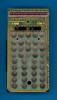
When the SR-51 was formally
introduced in January 1975 it still used the bold printing for the shifted 2nd-functions while later
SR-51
sports a much finer printing.
Don't miss the rare SR-51 Clear-Case Prototype.
To reduce manufacturing costs and to give a similar appearance to the SR-52 and SR-56 calculators the SR-51 was replaced within few month with the SR-51A.
If you have additions to the above article please email: joerg@datamath.org.
© Joerg Woerner, September 21, 2024. No reprints without written permission.