DATAMATH CALCULATOR MUSEUM
|
|
DATAMATH CALCULATOR MUSEUM |
Characterization of NEC Single-chip Calculator Circuits - µPD946 Series
The DCM-50A Platform supports the Characterization of many Non-TI single-chip calculator circuits with up to 42-pin packages using the DCM-50A Playground DIL42 Adapter mounted on top of the DCM-50A PG Frame Carrier with the voltages VSS and VDD/VGG set to the appropriate levels. The µPD946 Series requires the DCM50A Playground KBD123 Keyboard with Switch Matrix due to their segment scanning of the keyboard matrix.

![]() Device-under-Test:
Device-under-Test:
| • Package Markings Top:
µPD946C R62236 • Package Markings Bottom: • Donor Calculator: Royal RSC-40, March 1976 |
Keyboard: The Royal RSC-40 makes use of a keyboard assembly with 24 plastic keys pushing small conductive carbon pills mounted in a large silicone rubber membrane against contacts etched on a double-sided phenolic PCB. The sliding switch for the Memory-Accumulate function of the calculator is directly wired to the Keyboard-PCB. All switches are arranged in a 10*4 matrix with 9 rows connected to the SA-SH and SDP Outputs (Segment Scan) and the columns connected to the NK, FK1, FK2 and LK Inputs (Keyboard Scan) of the µPD946 single-chip calculator circuit. The remaining row of the 10*4 matrix is connected directly to the positive supply voltage VSS.
Keyboard Matrix of the Royal RSC-40:
µPD946 | ||||
| NK | FK1 | FK2 | LK | |
| VSS | 0 | C | % | |
| SA | 1 | = (√x) |
||
| SB | 2 | MR | M+= | |
| SC | 3 | MC | M−= | |
| SD | 4 | + (PI) |
||
| SE | 5 | − (+/−) |
||
| SF | 6 | ÷ (1/x) |
||
| SG | 7 | × (x2) |
[ - ∑] | |
| SH | 8 | . | ||
| SDP | 9 | F | CE | |
![]() Display:
The Royal RSC-40 makes use of an 9-digit Itron DP95A
low-voltage Vacuum Fluorescent Display (VFD) connected directly to the
respective 9 Digit Outputs D1 to D9 and 8 Segment Outputs SA to SG and SDP of
the µPD946 and biased to approximately -28 Volts.
Display:
The Royal RSC-40 makes use of an 9-digit Itron DP95A
low-voltage Vacuum Fluorescent Display (VFD) connected directly to the
respective 9 Digit Outputs D1 to D9 and 8 Segment Outputs SA to SG and SDP of
the µPD946 and biased to approximately -28 Volts.
Display Layout:
| Itron DP95A |
|
|
| The Segment drivers A-G and DP (Decimal Point) are connected to the Itron DP95A display in the pictured way. Segment driver H is not connected to the display. | 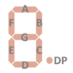 |
Display Fonts:
| Type | Calculator | Number Fonts | Decimal Separator |
Thousands Separator |
Entry Overflow |
Calculating Overflow |
Minus | Memory Indicator |
| µPD946 | Royal RSC-40 |
n.a. |


 Keyboard Scanning:
The µPD946 Series of single-chip calculator circuits utilizes nine segment
outputs and the VSS line to scan the keyboard. While scanning the
display, every three digits a short pause is inserted and all segment outputs
are briefly activated to detect key presses. The µPD946 inserts every three
completed display scan cycles a short sequential scan cycle, even if no keypress was detected.
Keyboard Scanning:
The µPD946 Series of single-chip calculator circuits utilizes nine segment
outputs and the VSS line to scan the keyboard. While scanning the
display, every three digits a short pause is inserted and all segment outputs
are briefly activated to detect key presses. The µPD946 inserts every three
completed display scan cycles a short sequential scan cycle, even if no keypress was detected.
Only the
necessary digit-driver outputs are activated, when displaying a "0." only D1
would be enabled. The provided recording shows first the moment the [2] key
located in the keyboard scan matrix of segment output SB and keyboard input NK
(K0)
was registered while displaying "1.". The next recording is showing the short pause between
two 3-digit keyboard scan cycles with all segments activated and six complete
display scan cycles to show the sequential scan cycles.

 Display
scanning: Display scanning is performed in D1 → D4 → D7 → D2 → D5 → D8 → D3
→ D6 → D9 direction at a rate of about 320 Hz. A short pause for parallel
keyboard scanning is inserted every three digits:
Display
scanning: Display scanning is performed in D1 → D4 → D7 → D2 → D5 → D8 → D3
→ D6 → D9 direction at a rate of about 320 Hz. A short pause for parallel
keyboard scanning is inserted every three digits:
|
• State Time = 1 Clock =
0.020 ms @ CK=50 kHz • Digit Time = 16 States = 0.320 ms @ CK=50 kHz • Keyboad Time = 4 States = 0.080 ms @ CK=50 kHz • Scan Time = 9 Digit Times + 3 Keyboard Times = 3.120 ms @ CK=50 kHz |

![]() Device-under-Test:
Device-under-Test:
| • Package Markings Top:
µPD947C R5X096 • Package Markings Bottom: • Donor Calculator: Royal 91K (Model UA122), September 1975 |
Keyboard: The Royal 91K (Model UA122) makes use of a keyboard assembly with 24 spring-supported plastic keys pushing small fingers on stamped sheet-metal pieces against contacts etched on a single-sided phenolic PCB. Additionally includes the keyboard assembly two 2-position sliding switches for power, and auto-summation and one 3-position sliding switch for decimal point setting. All switches are arranged in a 10*4 matrix with 9 rows connected to the SA-SH and SDP Outputs (Segment Scan) and the columns connected to the NK, FK1, FK2 and LK Inputs (Keyboard Scan) of the µPD947 single-chip calculator circuit. The remaining row of the 10*4 matrix is connected directly to the positive supply voltage VSS.
Keyboard Matrix of the Royal 91K (Model UA122):
µPD947 | ||||
| NK | FK1 | FK2 | LK | |
| VSS | 0 | C | % | |
| SA | 1 | = | ||
| SB | 2 | MOUT | M+ | [F234] |
| SC | 3 | CM | M− | [F234] |
| SD | 4 | + | ||
| SE | 5 | (−) | − | |
| SF | 6 | ÷ | ||
| SG | 7 | × | [ - ∑] | |
| SH | 8 | . | ||
| SDP | 9 | CI | ||
![]() Display:
The Royal 91K (Model UA122) makes use of an 9-digit Futaba 9-ST-12
low-voltage Vacuum Fluorescent Display (VFD) connected directly to the
respective 9 Digit Outputs D1 to D9 and 8 Segment Outputs SA to SG and SDP of
the µPD947 and biased to approximately -28 Volts.
Display:
The Royal 91K (Model UA122) makes use of an 9-digit Futaba 9-ST-12
low-voltage Vacuum Fluorescent Display (VFD) connected directly to the
respective 9 Digit Outputs D1 to D9 and 8 Segment Outputs SA to SG and SDP of
the µPD947 and biased to approximately -28 Volts.
Display Layout:
| Futaba 9-ST-12 |
|
|
| The Segment drivers A-G and DP (Decimal Point) are connected to the Futaba 9-ST-12 display in the pictured way. Segment driver H is not connected to the display. | |
Display Fonts:
| Type | Calculator | Number Fonts | Decimal Separator |
Thousands Separator |
Entry Overflow |
Calculating Overflow |
Minus | Memory Indicator |
| µPD947 | Royal 91K (UA122) |
n.a. |


 Keyboard Scanning: The µPD946
Series of single-chip calculator circuits utilizes nine
segment outputs and the VSS line to scan the keyboard. While scanning
the display, every three digits a short pause is inserted and all segment
outputs are briefly activated to detect key presses. The µPD946 inserts every
three completed display scan cycles a short sequential scan cycle, even if no keypress was detected. The µPD947 uses a modified approach because the
3-position sliding switch for the decimal point setting will always generate a
keypress. The provided recording shows the moment the [2] key located in the
keyboard scan matrix of segment output SB and keyboard input NK (K0) was registered
while displaying '2.'.
Keyboard Scanning: The µPD946
Series of single-chip calculator circuits utilizes nine
segment outputs and the VSS line to scan the keyboard. While scanning
the display, every three digits a short pause is inserted and all segment
outputs are briefly activated to detect key presses. The µPD946 inserts every
three completed display scan cycles a short sequential scan cycle, even if no keypress was detected. The µPD947 uses a modified approach because the
3-position sliding switch for the decimal point setting will always generate a
keypress. The provided recording shows the moment the [2] key located in the
keyboard scan matrix of segment output SB and keyboard input NK (K0) was registered
while displaying '2.'.
Only the
necessary digit-driver outputs are activated, when displaying a "0." only D1
would be enabled. The provided recordings are showing the short pause between
two 3-digit keyboard scan cycles with all segments activated and a six complete
display scan cycles to show the missing sequential scan cycles.

 Display
scanning: Display scanning is performed in D1 → D4 → D7 → D2 → D5 → D8 → D3
→ D6 → D9 direction at a rate of about 320 Hz. A short pause for parallel keyboard
scanning is inserted every three digits:
Display
scanning: Display scanning is performed in D1 → D4 → D7 → D2 → D5 → D8 → D3
→ D6 → D9 direction at a rate of about 320 Hz. A short pause for parallel keyboard
scanning is inserted every three digits:
|
• State Time = 1 Clock =
0.020 ms @ CK=50 kHz • Digit Time = 16 States = 0.320 ms @ CK=50 kHz • Keyboard Time = 4 States = 0.080 ms @ CK=50 kHz • Scan Time = 9 Digit Times + 3 Keyboard Times = 3.120 ms @ CK=50 kHz |

![]() Device-under-Test:
Device-under-Test:
| • Package Markings Top:
µPD278C R61066 • Package Markings Bottom: • Donor Calculator: Olympia CD44S, March 1976 |
Keyboard: The Olympia CD44S makes use of a keyboard assembly with 24 plastic keys pushing small fingers on stamped sheet-metal pieces against contacts etched on a single-sided phenolic PCB. The sliding power switch of the calculator is integrated on the Keyboard-PCB, too. All switches are arranged in a 10*3 matrix with 9 rows connected to the SA-SH and SDP Outputs (Segment Scan) and the columns connected to the NK, FK1 and FK2 Inputs (Keyboard Scan) of the µPD278 single-chip calculator circuit. The remaining row of the 10*3 matrix is connected directly to the positive supply voltage VSS.
Keyboard Matrix of the Olympia CD44S:
µPD278 | ||||
| NK | FK1 | FK2 | CH2 | |
| VSS | 0 | % | ||
| SA | 1 | = | ||
| SB | 2 | M+ | ||
| SC | 3 | M− | ||
| SD | 4 | + | ||
| SE | 5 | R | − | |
| SF | 6 | . | ÷ | |
| SG | 7 | +/− | × | |
| SH | 8 | RM CM |
||
| SDP | 9 | √x | C | |
![]() Display:
The Olympia CD44S makes use of an 9-digit Futaba 9-ST-10
low-voltage Vacuum Fluorescent Display (VFD) connected directly to the
respective 9 Digit Outputs D1 to D9 and 8 Segment Outputs SA to SG and SDP of
the µPD278 and biased to approximately -28 Volts.
Display:
The Olympia CD44S makes use of an 9-digit Futaba 9-ST-10
low-voltage Vacuum Fluorescent Display (VFD) connected directly to the
respective 9 Digit Outputs D1 to D9 and 8 Segment Outputs SA to SG and SDP of
the µPD278 and biased to approximately -28 Volts.
Display Layout:
| Futaba 9-ST-10 |
|
|
| The Segment drivers A-G and DP (Decimal Point) are connected to the Futaba 9-ST-10 display in the pictured way. Segment driver H is not connected to the display. | |
Display Fonts:
| Type | Calculator | Number Fonts | Decimal Separator |
Thousands Separator |
Entry Overflow |
Calculating Overflow |
Minus | Memory Indicator |
| µPD278 | Olympia CD44S |
n.a. |


 Keyboard Scanning:
The µPD278 single-chip calculator circuit utilizes nine segment
outputs and the VSS line to scan the keyboard. While scanning the
display, every three digits a short pause is inserted and all segment outputs
are briefly activated to detect key presses.
Keyboard Scanning:
The µPD278 single-chip calculator circuit utilizes nine segment
outputs and the VSS line to scan the keyboard. While scanning the
display, every three digits a short pause is inserted and all segment outputs
are briefly activated to detect key presses.
Only the
necessary digit-driver outputs are activated, when displaying a "0." only D1
would be enabled. The provided recording shows the moment the [2] key located in
the keyboard scan matrix of segment output SB and keyboard input NK (K0 was
registered while displaying '2.'.

 Display
scanning: Display scanning is performed in D1 → D4 → D7 → D2 → D5 → D8 → D3
→ D6 → D9 direction at a rate of about 320 Hz. A short pause for parallel
keyboard scanning is inserted every three digits:
Display
scanning: Display scanning is performed in D1 → D4 → D7 → D2 → D5 → D8 → D3
→ D6 → D9 direction at a rate of about 320 Hz. A short pause for parallel
keyboard scanning is inserted every three digits:
|
• State Time = 1 Clock =
0.020 ms @ CK=50 kHz • Digit Time = 16 States = 0.320 ms @ CK=50 kHz • Keyboard Time = 4 States = 0.080 ms @ CK=50 kHz • Scan Time = 9 Digit Times + 3 Keyboard Times = 3.120 ms @ CK=50 kHz |
If you have additions to the above article please email: joerg@datamath.org.
© Joerg Woerner, March 2, 2025. No reprints without written permission.