DATAMATH CALCULATOR MUSEUM
|
DATAMATH CALCULATOR MUSEUM |
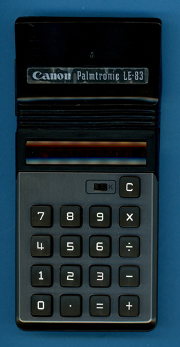
Canon LE-83 (Display Version 1)
| Date of introduction: | January 1974 | Display technology: | LED-stick |
| New price: | $44.95 | Display size: | 8 |
| Size: | 6.1" x 2.9" x 1.0" 154 x 74 x 25 mm3 |
||
| Weight: | 5.0 ounces, 142 grams | Serial No: | 652842 |
| Batteries: | 4*AA Alkaline | Date of manufacture: | mth 05 year 1974 |
| AC-Adapter: | Canon AD-1 | Origin of manufacture: | Japan |
| Precision: | 8 | Integrated circuits: | TMS0101 |
| Logic: | Chain | Displays: | ANTEX SK-3-307/8 |
| Memories: | |||
| Program steps: | Courtesy of: | Joerg Woerner | |
| Download manual: | |
![]()
 Canon
introduced in January 1974 with the LE-83 their first calculator with an MSRP (Manufacturer's Suggested Retail Price) below $50.
While we consider the LE-83 and its stablemates as members of the 4th
generation of Canon's product portfolio of Battery-powered Handheld Calculators with
Light Emitting Diode (LED) display, does it reuse with the TMS0101
single-chip calculator circuit some technology of the 2nd generation
LE-80:
Canon
introduced in January 1974 with the LE-83 their first calculator with an MSRP (Manufacturer's Suggested Retail Price) below $50.
While we consider the LE-83 and its stablemates as members of the 4th
generation of Canon's product portfolio of Battery-powered Handheld Calculators with
Light Emitting Diode (LED) display, does it reuse with the TMS0101
single-chip calculator circuit some technology of the 2nd generation
LE-80:
|
• 1st Generation:
LE-10 • 2nd Generation: LE-80, LE-80M, LE-80R, LE-82 • 3rd Generation: LE-81M, LE-100, F-5, FC-80 • 4th Generation: LE-83, LE-84 and LE-85 |
With the MSRP of the LE-80 in 1973 still around $100, Canon's engineering team needed to dig deep into the cost-reduction toolbox while designing the $50 LE-83 and it shows! Canon decided to use with the TMS0701 the 2nd generation of the TMS0101 chip which allows to drive the segments of the LED display directly. Having the LED display in 1974 as the main cost driver of portable calculators, Canon opted for an 8-digit display and one additional discrete round LED for the minus sign instead the 9-digit display used with LE-80 but missed changing the code of the TMS0101. With the TMS0101 clearly developed for displays with a leading 9th digit and Canon using just a discrete LED to the right of the 1st digit instead a full character instead, the LE-83 expressed some strange behavior:
|
• Negative numbers with 1 to 7 digits show a minus sign to the left of the number • Negative numbers with 8 digits show a minus "dot" to the right of the number • Overflow of the calculating result, displayed with the TMS0101 as |
Canon's engineering team fixed this flaw with the LE-84 and LE-85 using two different approaches, consequently creating a rather divers portfolio:
| Calculator | Features | Display | Overflow |
| LE-83 | [CONST] | NONE | |
| LE-84 | FLASHING | ||
| LE-85 | [sqrX][%±] |
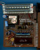
 Dismantling the featured Canon LE-83 manufactured in
May 1974
by Canon in Japan reveals a rather compact design with three printed circuit
boards (PCBs) for main electronics, display, and keyboard powered by four disposable Alkaline batteries. The Main-PCB is centered around a
Texas Instruments single-chip calculator circuit and supported by a
myriad of discrete components:
Dismantling the featured Canon LE-83 manufactured in
May 1974
by Canon in Japan reveals a rather compact design with three printed circuit
boards (PCBs) for main electronics, display, and keyboard powered by four disposable Alkaline batteries. The Main-PCB is centered around a
Texas Instruments single-chip calculator circuit and supported by a
myriad of discrete components:
|
• Calculating Unit -
TMS0101 (TMS0701) single-chip calculator circuit • Display Driver - No Segment Drivers and discrete Digit Drivers with two Transistor Arrays • Clock signal generation for TMS0101 with discrete components • Power converter with discrete components and transformer • 17-pin connector to the Display-PCB (16 pins used) • 20-pin connector to the Keyboard-PCB (18 pins used) |
![]() Calculating Unit: The LE-83 makes use of a 2nd
generation TMS0101 single-chip calculator
circuit, also known as TMS0701 and derived from the TMS1802,
better known as first "calculator-on-a-chip".
Calculating Unit: The LE-83 makes use of a 2nd
generation TMS0101 single-chip calculator
circuit, also known as TMS0701 and derived from the TMS1802,
better known as first "calculator-on-a-chip".
![]() Display: Texas Instruments introduced together with the
TMS0100 calculator chip two pre-configured
LED (Light-Emitting-Diode) modules (DIS40,
DIS95) based on the
TIL360 arrays and the corresponding segment drivers (SN75491) and digit drivers (SN75492). Most early 8-digit designs
like the LE-80 made use of these parts
exhibiting two disadvantages:
Display: Texas Instruments introduced together with the
TMS0100 calculator chip two pre-configured
LED (Light-Emitting-Diode) modules (DIS40,
DIS95) based on the
TIL360 arrays and the corresponding segment drivers (SN75491) and digit drivers (SN75492). Most early 8-digit designs
like the LE-80 made use of these parts
exhibiting two disadvantages:
|
• SN75491, SN75492 - Limited to designs with 5 or 6 batteries • TIL360 - Cost driver number one in the calculator design |
Texas Instruments consequently introduced with the SN75493 and SN75494 revised display drivers optimized for designs with 3 or 4 batteries but the true innovation could be observed with the technology how to manufacture the 9-digit LED displays used with early four-function calculators:
|
• 1972: Two Hermetic Multi-Digit Calculator Numeric Seven-Segment LED Displays soldered onto
a PCB • 1973: Nine Seven-Segment LED Displays soldered onto a PCB • 1974: Nine Seven-Segment LED Display Chips bonded onto a PCB • 1975: Nine small Seven-Segment LED Display Chips bonded onto a PCB with additional magnifying lens • 1976: LED Displays near extinguished by VFD and LCD technology |
 On the tireless, never ending quest to squeeze the last penny
out of the manufacturing costs of electronic calculators, Canon used with the
LE-83 four different LED display manufacturers and technologies. With more than
a dozen of LE-83, LE-84 and LE-85 calculators examined, we understood that Canon marked the backside of the
4th Generation of Battery-powered Handheld Calculators accordingly, as
of today we identified the following matrix:
On the tireless, never ending quest to squeeze the last penny
out of the manufacturing costs of electronic calculators, Canon used with the
LE-83 four different LED display manufacturers and technologies. With more than
a dozen of LE-83, LE-84 and LE-85 calculators examined, we understood that Canon marked the backside of the
4th Generation of Battery-powered Handheld Calculators accordingly, as
of today we identified the following matrix:
| Display Technology |
Label | LE-83 RSEG - RDIG |
LE-84 RSEG - RDIG |
LE-85 RSEG - RDIG |
| ANTEX SK-3-307/8 COB with Ceramic Substrate Magnifying Lens |
51 |
Version 1 220 Ohm 5.6k Ohm |
Version 1 390 Ohm 2.2k Ohm |
- - - |
| Monsanto MAN-3A/8 7-Segment Displays on PCB No Magnifying Lens |
52 |
Version 2 82 Ohm 5.6k Ohm |
- - - |
- - - |
| ANTEX SK-2-151/8 COB with Ceramic Substrate Magnifying Lens |
53 |
- - - |
Version 2 390 Ohm 2.2k Ohm |
- - - |
| ROHM LAB-B-2/8 COB on PCB, No Mask Magnifying Lens |
54 |
Panther 220 Ohm 5.6k Ohm |
Version 3 220 Ohm 2.2k Ohm |
- - - |
| ROHM LAB-B-2/9 COB on PCB, No Mask Magnifying Lens |
54 |
- - - |
- - - |
Version 1 220 Ohm 2.2k Ohm |
| Litronix
D-3034/8 COB on PCB, Gray Mask Magnifying Lens |
__ |
Version 3 220 Ohm 5.6k Ohm |
- - - |
- - - |
Note: Here at the Datamath Calculator Museum we use a "Version Index" for the different display modules located in the Canon LE-83, LE-84 and LE-85 calculators based on the round paper stickers but couldn't find out the chronological order of them.
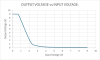
If your LE-83 uses resistors with a value of 2.2k Ohm instead of 5.6k Ohm as listed in the table above, your calculator was modified after April 1975 - Canon sent out a notice to their Service Partners to replace not only these resistors but even the digit driver transistors from 2N5449 to 2SC1641 in case the customers are complaining about a dim LED display. To better understand the influence of the digit driver transistors on the display brightness, we first measured the current gains (hFE) of both transistors and two of the optional Transistor Arrays TA1 and TA2. In a next step we measured their Output Voltage vs Input Voltage transfer functions with an automated setup originally created for 75492-style devices. Here at the Datamath Calculator Museum we use this transfer function as an easy obtainable "Signature" of the underlying circuit design and manufacturing processes of digit drivers:
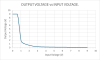
| Digit Driver | hFE | Signature |
| 2N5449 | 110 |
 |
| 2SC1641 | 510 |
 |
| TA1 | 160 |
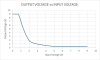 |
| TA2 | 260 |
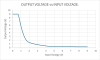 |
It is obvious that hFE of the original 2N5449 BJT is on the lower side, meaning the digit drivers won't fully saturate with less than 1 mA base current and Canon consequently increased both base current with lowering the limiting resistor from 5.6k Ohm to 2.2k Ohm and increasing hFE with changing the transistor type.
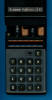
![]() The
featured LE-83 manufactured in May 1974 makes use of an ANTEX SK-3-307 8-Digit
display module with eight 7-Segment displays chips bonded onto a Ceramic
Substrate and
magnified with a clear plastic lens. The display module is connected with 16
pins to the Main-PCB and follows the industry standard pinout of 9-Digit modules
with the leftmost pin (Digit D9) unconnected. A small red LED with long leads is
soldered directly onto the Main-PCB of the LE-83 calculator and bended over the
display module to act as Minus "dot" for 8-digit numbers.
The
featured LE-83 manufactured in May 1974 makes use of an ANTEX SK-3-307 8-Digit
display module with eight 7-Segment displays chips bonded onto a Ceramic
Substrate and
magnified with a clear plastic lens. The display module is connected with 16
pins to the Main-PCB and follows the industry standard pinout of 9-Digit modules
with the leftmost pin (Digit D9) unconnected. A small red LED with long leads is
soldered directly onto the Main-PCB of the LE-83 calculator and bended over the
display module to act as Minus "dot" for 8-digit numbers.
 Display Driver: The Main-PCB of the featured LE-83
manufactured in May 1974 makes use of nine Transistors with supporting
Resistors as discrete Digit Drivers for the LED display while the TMS0701 chip
drives the Segments directly. The layout of the PCB would support two Transistor
Arrays TA1 and TA2 with four, respective five transistors bonded and
encapsulated into a small module, too.
Display Driver: The Main-PCB of the featured LE-83
manufactured in May 1974 makes use of nine Transistors with supporting
Resistors as discrete Digit Drivers for the LED display while the TMS0701 chip
drives the Segments directly. The layout of the PCB would support two Transistor
Arrays TA1 and TA2 with four, respective five transistors bonded and
encapsulated into a small module, too.
Clock: While the nominal clock frequency of the TMS0700 single-chip calculator circuit is specified with 250 kHz, uses the LE-83 a much slower pace to reduce overall power consumption of the product slightly. The astable multivibrator using two discrete transistors operates at a frequency between 100 kHz and 150 kHz, we observed with the featured LE-83 manufactured in May 1974 a clock frequency of 132 kHz.
Power Supply: The LE-83 is powered by four disposable AA-sized 1.5 Volt batteries and can be operated with an external, DC adapter, too. The PCB of the calculator hosts a discrete power converter to generate the VDD and VGG supply voltages for the TMS0101 chip. To reduce power consumption of the calculator, the VGG voltage is pulsed with the clock frequency between VDD and its peak level. We observed with the featured calculator manufactured in May 1974 voltages of VDD = -6.5 V and VGG(pk) = -13.2 V while operated with VBAT = 6.0 V. The LED displays of the LE-83 are operated directly from the battery voltage and we measured the current consumption of the featured calculator with:
| Mode | Display | Current VBAT = 6.0 V |
Clock Frequency |
| Calculating | 0. | 26 mA | 132 kHz |
| Calculating | 88888888. | 59 mA | 132 kHz |
The power consumption for the featured Canon LE-83 results in about 160 mW displaying a '0.' and 350 mW with all segments but the minus sign illuminated compared to the LE-84 (Display Version 1) sporting the same LED display with 100 mW and 320 mW, respectively.

 Keyboard: The keyboard of the LE-83 uses
spring-supported plastic keys pushing a small conductive rubber element against
two contacts etched on a single-sided phenolic PCB combining both long-travel
keys with reasonable manufacturing costs while maintaining longevity of the
calculator. The keyboard module is connected with a short 18-pin flat-cable to
the Main-PCB.
Keyboard: The keyboard of the LE-83 uses
spring-supported plastic keys pushing a small conductive rubber element against
two contacts etched on a single-sided phenolic PCB combining both long-travel
keys with reasonable manufacturing costs while maintaining longevity of the
calculator. The keyboard module is connected with a short 18-pin flat-cable to
the Main-PCB.
Here at the Datamath Calculator Museum we classify the featured
LE-83 as Display Version 1.
The LE-83, LE-84, and LE-85 introduced in 1974 marked the last generation of calculators with LED displays in Canon's portfolio of Portable Handheld Calculators and the next product named LD-80 was sporting a green VFD (Vacuum-Fluorescent-Display) instead.
If you have additions to the above article please email: joerg@datamath.org.
© Joerg Woerner, December 5, 2001. No reprints without written permission.