DATAMATH CALCULATOR MUSEUM
|
DATAMATH CALCULATOR MUSEUM |
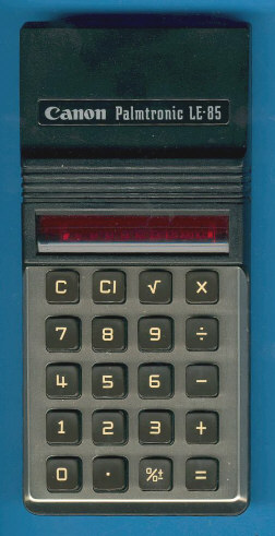
Canon LE-85
| Date of introduction: | 1974 | Display technology: | LED-stick |
| New price: | $39.95 (1975) | Display size: | 8 + Sign |
| Size: | 6.1" x 2.9" x 1.0" 154 x 74 x 25 mm3 |
||
| Weight: | 5.2 ounces, 147 grams | Serial No: | 506295 |
| Batteries: | 4*AA Alkaline | Date of manufacture: | mth 10 year 1974 |
| AC-Adapter: | Canon AD-1 | Origin of manufacture: | Taiwan |
| Precision: | 8 | Integrated circuits: | TMS0807 |
| Logic: | Chain | Displays: | ROHM LAB-B-2/9 |
| Memories: | |||
| Program steps: | Courtesy of: | Joerg Woerner | |
| Download manual: | |
![]() When Texas Instruments introduced in Fall 1973 the successor
of the 1st Generation TMS0100 Product Family, they actually
diversified the portfolio into three different branches:
When Texas Instruments introduced in Fall 1973 the successor
of the 1st Generation TMS0100 Product Family, they actually
diversified the portfolio into three different branches:
|
•
TMS0600: Increased ROM (384 Words
* 11 Bits), Identical SAM (13 Digits Registers), external display drivers. Process shrink, higher functionality • TMS0700: Identical ROM (320 Words * 11 Bits), Identical SAM (13 Digits Registers), external display drivers. Process shrink, identical functionality, cost reduction of IC • TMS0800: Identical ROM (320 Words * 11 Bits), Reduced SAM (11 Digits Registers), integrated segment drivers. Process shrink, reduced functionality, higher integration |
Canon Inc. took immediately advantage of the new portfolio and added functionality like adding a memory and square root function to the TMS0600-based LE-81M or adding 10-digit capabilities to the TMS0700-based LE-100. But more important was the introduction of the compact LE-83, dropping the rechargeable battery pack and reducing manufacturing costs dramatically. While the LE-83 was still based on a TMS0700 chip, used the more capable and yet more economic LE-84 the advantages of the TMS0800. Final step in cost-down was this LE-85, using the TMS0800, too but manufactured in Taiwan instead of Japan to take advantage of the lower labor costs.


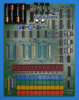
 Dismantling
the featured Canon LE-85 calculator manufactured in October 1974 in Taiwan
requires the removal of two screws located under the battery compartment and is
instantly rewarding with the very high manufacturing quality of Canon products.
Every part of the calculator feels very substantial and well engineered, from
the sliding battery cover to the keyboard assembly. Comparing the weight of the
LE-85 with a Commodore 885D introduced in the same time and using an identical
calculator chip, results in 147 grams (5.2 ounces) vs 106 grams (3.7 ounces).
Dismantling
the featured Canon LE-85 calculator manufactured in October 1974 in Taiwan
requires the removal of two screws located under the battery compartment and is
instantly rewarding with the very high manufacturing quality of Canon products.
Every part of the calculator feels very substantial and well engineered, from
the sliding battery cover to the keyboard assembly. Comparing the weight of the
LE-85 with a Commodore 885D introduced in the same time and using an identical
calculator chip, results in 147 grams (5.2 ounces) vs 106 grams (3.7 ounces).
 We
started on our quest to
Record the ROM
Content of the TMS0807 single-chip calculator circuit deeper into the
internals of the featured Canon LE-85 and made some surprising findings:
We
started on our quest to
Record the ROM
Content of the TMS0807 single-chip calculator circuit deeper into the
internals of the featured Canon LE-85 and made some surprising findings:
|
• The printed circuit board (PCB)
can accommodate different display drivers • The 8-digit LED display of the LE-84 was replaced with a 9-digit display |
![]() Calculating Unit: The TMS0807 is a member of the TMS0800 Product Family and tracing back to
the TMS1802NC, the first available standard calculator building block on a chip,
later renamed into TMS0102. The TMS0800
kept the size of the Instruction ROM (Read-Only Memory), but decreased the Data
Memory from 13 Digits Registers to 11 Digit Registers and added both integrated
segment drivers for the LED display and a clock generator.
Calculating Unit: The TMS0807 is a member of the TMS0800 Product Family and tracing back to
the TMS1802NC, the first available standard calculator building block on a chip,
later renamed into TMS0102. The TMS0800
kept the size of the Instruction ROM (Read-Only Memory), but decreased the Data
Memory from 13 Digits Registers to 11 Digit Registers and added both integrated
segment drivers for the LED display and a clock generator.
With low-cost, battery operated LED calculators in mind, Texas Instruments added a so-called Timeout feature to the TMS0800 devices. When no key presses are detected for about 20 seconds, the display blanks out and shows only a '-' in the leftmost digit to reduce power consumption of the calculator. Looking closely at the PCB traces of the featured Canon LE-85, you'll recognize that Pin 10 (WDK) and Pin 8 (KN) are connected to effectively disable the Timeout feature.
![]()
![]() Display: This
Canon LE-85 calculator manufactured
in October 1974 makes use of a ROHM Semiconductor
LAB-B-2 9-Digit display module with nine 7-Segment displays chips bonded onto a PCB and magnified with a clear plastic lens. The display module is connected with 17 pins to the Main-PCB
and follows the industry standard pinout.
Display: This
Canon LE-85 calculator manufactured
in October 1974 makes use of a ROHM Semiconductor
LAB-B-2 9-Digit display module with nine 7-Segment displays chips bonded onto a PCB and magnified with a clear plastic lens. The display module is connected with 17 pins to the Main-PCB
and follows the industry standard pinout.


![]() Display Driver: The PCB of the disassembled
Canon LE-85 makes use of two hybrid modules with five, respective four
transistors, each. Looking closer at the layout of the PCB, you'll notice that
there are "spare" holes below the two hybrid modules to accommodate discrete NPN
bipolar junction transistors (BJTs), too. Understanding that the circuit diagram
of the Canon LE-85 includes series resistors with 2.2k Ohm between the digit
driver outputs and the Base connection of the corresponding BJTs, we felt safe
to measure the Output Voltage vs
Input Voltage transfer function of the hybrid modules with an automated setup originally created for
75492-style devices. Here at the Datamath Calculator Museum we use this
transfer function as an easy obtainable "Signature"
of the underlying circuit design and manufacturing processes of digit drivers. In
a first step we tested one transistor of the hybrid modules each with a DCA75 Advanced
Semiconductor Analyzer from Peak Electronic Design. The DCA75 easily recognized
the transistors as NPN BJT and measured a current gain (hFE) of
around 160 for the first transistor of the 5-channel hybrid module and around
260 for the first transistor of the 4-channel hybrid module.
Display Driver: The PCB of the disassembled
Canon LE-85 makes use of two hybrid modules with five, respective four
transistors, each. Looking closer at the layout of the PCB, you'll notice that
there are "spare" holes below the two hybrid modules to accommodate discrete NPN
bipolar junction transistors (BJTs), too. Understanding that the circuit diagram
of the Canon LE-85 includes series resistors with 2.2k Ohm between the digit
driver outputs and the Base connection of the corresponding BJTs, we felt safe
to measure the Output Voltage vs
Input Voltage transfer function of the hybrid modules with an automated setup originally created for
75492-style devices. Here at the Datamath Calculator Museum we use this
transfer function as an easy obtainable "Signature"
of the underlying circuit design and manufacturing processes of digit drivers. In
a first step we tested one transistor of the hybrid modules each with a DCA75 Advanced
Semiconductor Analyzer from Peak Electronic Design. The DCA75 easily recognized
the transistors as NPN BJT and measured a current gain (hFE) of
around 160 for the first transistor of the 5-channel hybrid module and around
260 for the first transistor of the 4-channel hybrid module.
 Next
we retrieved the Signatures of the tested transistors and compared it with a
discrete 2N3904 NPN BJT with a current gain of around 180. Comparing the three
Signatures demonstrates clearly that the two hybrid modules contain just
discrete General Purpose NPN BJTs bonded on a ceramic substrate and no other
components like resistors or diodes.
Next
we retrieved the Signatures of the tested transistors and compared it with a
discrete 2N3904 NPN BJT with a current gain of around 180. Comparing the three
Signatures demonstrates clearly that the two hybrid modules contain just
discrete General Purpose NPN BJTs bonded on a ceramic substrate and no other
components like resistors or diodes.
Clock: The featured Canon LE-85 makes use of the internal clock
oscillator of the TMS0800 chip, we identified a resistor with 100 kOhm connected
between Pin 14 (REXT//Clock Select) of the TMS0807 and the VDD power supply line, resulting in a clock frequency of about of
180 kHz.
Power Supply: The Canon LE-85 is powered by four disposable AA-sized 1.5 Volt batteries and can be operated with an external, DC adapter, too. The PCB of the calculator hosts a discrete power converter to generate the VDD and VGG supply voltages for the TMS0807 chip. We observed with the featured calculator manufactured in October 1974 voltages of VDD = -9.2 V and VGG = -16.1 V while operated with VBAT = 6.0 V. While reverse-engineering the circuit diagram of the calculator, we noticed the rather low 2k2 Ohm series resistors for the digit drivers, usually a sign of high segment currents of the LED display. The PCB of the featured calculator confirmed our suspicion, the populated segment resistors have only 220 Ohm. Consequently did we measure a higher than advertised operating current of the calculator:
| Mode | Display | Current VBAT = 3.0 V |
Clock Frequency |
| Calculating | 0. | 22 mA | 180 kHz |
| Calculating | 88888888. | 77 mA | 180 kHz |
The power consumption for the featured Canon LE-85 results in about 130 mW displaying a '0.' and 460 mW with all segments but the minus sign illuminated. Barely within the 500 mW stated on the label of the calculator but still beating the Commodore Model 885D calculator using the same TMC0807 single-chip calculator circuit but powered with a disposable 9 V battery. To fully understand the power budget of the Canon LE-85, we not only calculated the theoretical segment and digit currents of the featured calculator, we measured them dynamically with the calculator operating.
With the operating current numbers from the featured Canon LE-85, we calculate in a first step the average current per segment. The differences between the '0.' and '88888888.' displays are 50 segments and 55 mA, or 1.1 mA per segment. The TMS0807 chip is scanning the digits and segments with a 1:10 duty cycle, resulting in 11 mA average segment current per Digit Time. Each Digit Time has 11 State Times with S1 and S11 blanking the segments for a peak current of 13.4 mA per segment and around 94 mA per digit. The high-efficiency LED chips used with the calculator have a voltage drop of around 1.7 V at 13.4 mA segment current, and with a 6 Volt battery the sum of all other components in the loop will "burn" around 4.3 V:
| • TMS0807 segment driver (1.0 V) - 220 Ohm resistor (3.0 V) - LED chip (1.7 V) - hybrid module digit driver (0.3 V) |
The Commodore 885D calculator on the other hand is using a 9 Volt battery for the LED driver circuitry and consequently needs to "burn" around 7 V between power supply and LED chips. And the true master is Texas Instruments with its TI-2500-II design, using only two 1.5 Volt batteries and "burning" just 1.3 V between power supply and LED chips.
Keyboard: The Canon LE-85 calculator makes use of a keyboard module with a single-sided phenolic-substrate PCB with gold-plated traces for the contacts and spring-loaded conductive rubber elements for its injection molded plastic keys. This technology used by Canon with many calculators form the early 1970s proved over time as very reliable.
 With
the DCM-50A Platform developed to
Characterize and
Reverse-engineer
Single-chip Calculator Circuits we could proof that the
Program Code of the
TMS0807 is tracing back to the
TMS0803 but dropped its Decimal
Alignment feature in lieu of the square root function. Other changes are the
implementation of the percent function and a different programming of the
segment decoder PLA.
With
the DCM-50A Platform developed to
Characterize and
Reverse-engineer
Single-chip Calculator Circuits we could proof that the
Program Code of the
TMS0807 is tracing back to the
TMS0803 but dropped its Decimal
Alignment feature in lieu of the square root function. Other changes are the
implementation of the percent function and a different programming of the
segment decoder PLA.
From the technology the LE-85 is similar to the Exactra-19 introduced by TI same time.
The LE-85 and its sibling LE-84 were the last two pocket calculators developed by Canon and using red LED (Light Emitting Diode) displays.
Canon's next calculator generation starting with the Panther D and LD-80 used VFDs (Vacuum Fluorescent Displays). Main advantage of this technology was that time both lower power consumption and cheaper manufacturing costs.
If you have additions to the above article please email: joerg@datamath.org.
© Joerg Woerner, April 5, 2004. No reprints without written permission.