DATAMATH CALCULATOR MUSEUM
|
DATAMATH CALCULATOR MUSEUM |
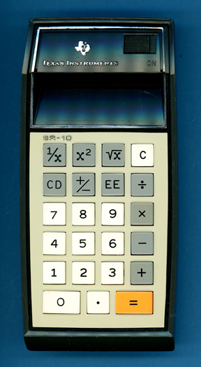
Texas Instruments SR-10 Version 2
| Date of introduction: | December 1973 | Display technology: | LED modules + lens |
| New price: | $89.99 | Display size: | 8 + 2 |
| Size: | 6.3" x 3.1" x
1.5" 158 x 78 x 38 mm3 |
||
| Weight: | 9.2 ounces, 262 grams | Serial No: | SR-10 1145770 |
| Batteries: | 3*AA NiCd | Date of manufacture: | mth 12 year 1973 |
| AC-Adapter: | AC9200, AC9130 | Origin of manufacture: | USA |
| Precision: | 8 | Integrated circuits: | TMS0120 (TMS0720), 2*SN75493, 2*SN75494 |
| Logic: | Chain | Displays: | DIS115F (12*DISXXX) |
| Memories: | |||
| Program steps: | Courtesy of: | Joerg Woerner | |
| Download manuals: | |
![]()
![]() This
SR-10 Version 2 can be distinguished from the original SR-10
Version 1 easily: The SR-10 logo of the original design was molded into the display frame
and painted silver, with this revised design it is molded into the keyboard
plate and painted black.
This
SR-10 Version 2 can be distinguished from the original SR-10
Version 1 easily: The SR-10 logo of the original design was molded into the display frame
and painted silver, with this revised design it is molded into the keyboard
plate and painted black.
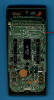
 Dismantling this SR-10
Version 2 manufactured in
December 1973 by
Texas Instruments in the United States reveals a complex design with three
printed circuit boards (PCBs) for main electronics, display, and keyboard
powered by three AA-sized rechargeable NiCd batteries. The Main-PCB sports not
only five familiar looking Integrated Circuits (ICs) but a myriad of discrete
components in a from the Datamath well known arrangement:
Dismantling this SR-10
Version 2 manufactured in
December 1973 by
Texas Instruments in the United States reveals a complex design with three
printed circuit boards (PCBs) for main electronics, display, and keyboard
powered by three AA-sized rechargeable NiCd batteries. The Main-PCB sports not
only five familiar looking Integrated Circuits (ICs) but a myriad of discrete
components in a from the Datamath well known arrangement:
|
• Calculating Unit - TMS0120 single-chip calculator circuit • Display Driver - 2*SN75493 Segment Drivers and 2*SN75494 Digit Drivers • Clock signal generation for TMS0120 with discrete components • Power converter with discrete components and transformer • 21-pin connector to the Display-PCB • 15-pin connector to the Keyboard-PCB |
The only differences we spotted between the Main-PCB of this SR-10 Version 2 and an SR-10 Version 1 manufactured about 9 months earlier are the display drivers sporting the "standard" SN75xxx designation versus the "custom" SN27xxx designation.
![]() Calculating Unit: The
SR-10 makes use of the TMS0120 single-chip calculator circuit derived from the TMS1802,
better known as first "calculator-on-a-chip". Around July 1973 the first TMS0100 designs were ported to an 8-micron process and internally renamed to
TMS0700 but still marked on the outside of the package with TMS01XX. The
featured SR-10 Version 2 manufactured in December 1973 uses according to its
marking on the bottom of the package a TMS0720.
Calculating Unit: The
SR-10 makes use of the TMS0120 single-chip calculator circuit derived from the TMS1802,
better known as first "calculator-on-a-chip". Around July 1973 the first TMS0100 designs were ported to an 8-micron process and internally renamed to
TMS0700 but still marked on the outside of the package with TMS01XX. The
featured SR-10 Version 2 manufactured in December 1973 uses according to its
marking on the bottom of the package a TMS0720.
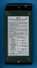
![]() Display: The featured SR-10 manufactured in December 1973 uses a
DIS115F Twelve-Digit display module with 12 individual DISXXX Seven-Segment displays and an integrated magnifying lens.
Display: The featured SR-10 manufactured in December 1973 uses a
DIS115F Twelve-Digit display module with 12 individual DISXXX Seven-Segment displays and an integrated magnifying lens.
![]()
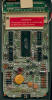
![]() Display Driver: The Main-PCB of the featured SR-10 manufactured in
December 1973 makes use of a total of four Display Drivers. The two
SN75493 Segment Drivers for four segments, each and the two
SN75494 Digit Drivers for six digits, each are improvements of the original
SN75491/SN75492
chips introduced with the TMS1802 but allow for operation at lower voltages.
Display Driver: The Main-PCB of the featured SR-10 manufactured in
December 1973 makes use of a total of four Display Drivers. The two
SN75493 Segment Drivers for four segments, each and the two
SN75494 Digit Drivers for six digits, each are improvements of the original
SN75491/SN75492
chips introduced with the TMS1802 but allow for operation at lower voltages.
Clock: While the nominal clock frequency of the TMS0100 single-chip calculator circuit is specified with 250 kHz, uses the SR-10 a slower pace to reduce overall power consumption of the product slightly. The astable multivibrator using two discrete transistors operates at a frequency between 150 kHz and 200 kHz, we observed with the featured SR-10 manufactured in December 1973 a clock frequency of 180 kHz.
Texas Instruments introduced in August 1973 with the TI-2500 Version 3 the approach of a dynamic switching of the clock frequency for the TMS0100 single-chip calculator circuit to conserve power between calculations. The astable multivibrator idles at a frequency of around 50 kHz but increases with the detection of a depressed keybutton for a short time to about 200 kHz to reduce execution time of the operations. Two diodes are connected between the keymatrix inputs KN (numbers) and KO (operations) and the oscillator to catch every entry of a number or function keys for a impressive reduction of power consumption.
Power Supply: The SR-10 is powered by three AA-sized rechargeable NiCd batteries resulting in a typical voltage between 3.0 V (completely depleted cells) and 4.5 V (while charging full cells). The Main-PCB hosts a power converter circuit centered around an astable multivibrator, step-up transformer and various diodes and capacitors to generate the supply voltages for the TMS0120 chip and the clock oscillator.
Battery Saver Circuit: To save battery power the LED display turns off automatically between 15 and 60 seconds after the last keyboard entry, except for the first digit (Digit D3 of TMS0120, LSD of Mantissa). If the display turns off while entering a problem, the display turns on automatically with the first keyboard entry. Depressing the [=] key brings back the last calculated display. Three diodes are connected between the keymatrix inputs KN (numbers), KO (operations) and KP ([1/x], [x2] and [sqr X]) and a simple monoflop to catch every entry of a number or function keys to keep the Digit Drivers enabled. If the monoflop time expires, the Digit Drivers sans Digit 3 are disabled for an impressive reduction of power consumption:
| Mode | Display | Current VBAT = 4.5 V |
Clock Frequency |
| Calculating | 0 | 61 mA | 180 kHz |
| Power Save | 0 | 61 mA | 180 kHz |
| Calculating | E88888888-88 | 124 mA | 180 kHz |
| Power Save | 8 | 72 mA | 180 kHz |
Keyboard: The Klixon™ type keyboard looks very similar to the Datamath calculator with some additional keys placed in the upper line. Later calculators like the SR-11 changed the style of the keys but kept the extreme wedge-style of the housing that was adopted for the scientific desktop calculators SR-20 and SR-22, too. The last portable scientific calculator with this wedge-design was introduced in October 1974 with the SR-16.
![]() The first series of the SR-10
shared the poor readability
of the TIL360
based
display with the early Datamath calculators.
The first series of the SR-10
shared the poor readability
of the TIL360
based
display with the early Datamath calculators.
![]() Texas
Instruments experimented with different solutions and created some prototypes
with lenses attached to the 6-digit LED-modules.
Texas
Instruments experimented with different solutions and created some prototypes
with lenses attached to the 6-digit LED-modules.
Later models used different LED-modules with an additional magnification lens.
Don't miss the rare SR-10 Clear-Case Prototype and
compare it with the SR-10 Version 2.
 Not only the appearance of the SR-10 and the used LED-modules changed during the life cycle of the calculator, a later cost-reduction redesign changed the Main-PCB completely and we differentiate between
four different SR-10 Versions manufactured in the United States between November 1972 and
June 1975:
Not only the appearance of the SR-10 and the used LED-modules changed during the life cycle of the calculator, a later cost-reduction redesign changed the Main-PCB completely and we differentiate between
four different SR-10 Versions manufactured in the United States between November 1972 and
June 1975:
| Version | Position of SR-10 logo |
Display Type |
Display Driver |
| SR-10 USA V1 | Display frame | 6-digit modules without lens |
4 ICs |
| SR-10 USA V1D2 | Display frame | single modules with lens |
4 ICs |
| SR-10 USA V2 | Keyboard | single modules with lens |
4 ICs |
| SR-10 USA V3 | Keyboard | single modules with lens |
2 ICs |
Here at the Datamath Calculator Museum we classify the featured SR-10 as Display Frame Version 2, PCB Type 2 and Display Type 2.
The SR-10 manufactured in Italy for the European market introduced a slightly different design of the housing.
The SR-10 was sold with different nameplates, don't miss the Radio Shack EC-425
and the Montgomery Ward
P300. If you are looking for a SR-10 with blue function keys, don't miss this
SR-10 Rebuilt.
If you have additions to the above article please email: joerg@datamath.org.
© Joerg Woerner, December 5, 2001. No reprints without written permission.