DATAMATH CALCULATOR MUSEUM
|
DATAMATH CALCULATOR MUSEUM |
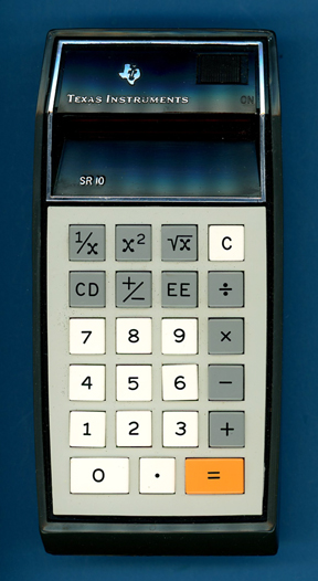
Texas Instruments SR-10 Version 1 (Display 2)
| Date of introduction: | February 1973 | Display technology: | LED modules |
| New price: | $149.95 | Display size: | 8 + 2 |
| Size: | 6.3" x 3.1" x
1.5" 158 x 78 x 38 mm3 |
||
| Weight: | 9.2 ounces, 262 grams | Serial No: | SR-10 64489 |
| Batteries: | 3*AA NiCd | Date of manufacture: | mth 03 year 1973 |
| AC-Adapter: | AC9200, AC9130 | Origin of manufacture: | USA |
| Precision: | 8 | Integrated circuits: | TMS0120, 2*SN27422, 2*SN27423 |
| Logic: | Chain | Displays: | DIS115F (12*DISXXX) |
| Memories: | |||
| Program steps: | Courtesy of: | Joerg Woerner | |
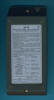
| Download manuals: | |
![]()
 Texas
Instruments introduced with the SR-10 their first scientific calculator just a few months
after the famous Datamath
or TI-2500. Today we wouldn't call it a scientific calculator, but it allowed to
enter and display numbers in the scientific
notation with an 8-digit Mantissa and a 2-digit Exponent. Texas Instruments targeted
obviously slide rules, guess what
the abbreviation "SR" in the designation stands for.
Texas
Instruments introduced with the SR-10 their first scientific calculator just a few months
after the famous Datamath
or TI-2500. Today we wouldn't call it a scientific calculator, but it allowed to
enter and display numbers in the scientific
notation with an 8-digit Mantissa and a 2-digit Exponent. Texas Instruments targeted
obviously slide rules, guess what
the abbreviation "SR" in the designation stands for.
While the appearance of the SR-10 with its bold wedge-style housing changed
dramatically from the smooth design with its rounded corners of the Datamath
developed by Industrial
Designer Fred M. Gore of Fred Gore & Associates, Inc, resembles the
internal construction a striking similarity.
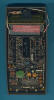
 Dismantling this early SR-10 manufactured in
March 1973 by
Texas Instruments in the United States reveals a complex design with three
printed circuit boards (PCBs) for main electronics, display, and keyboard
powered by three AA-sized rechargeable NiCd batteries. The Main-PCB sports not
only five familiar looking Integrated Circuits (ICs) but a myriad of discrete
components in a from the Datamath well known arrangement:
Dismantling this early SR-10 manufactured in
March 1973 by
Texas Instruments in the United States reveals a complex design with three
printed circuit boards (PCBs) for main electronics, display, and keyboard
powered by three AA-sized rechargeable NiCd batteries. The Main-PCB sports not
only five familiar looking Integrated Circuits (ICs) but a myriad of discrete
components in a from the Datamath well known arrangement:
|
• Calculating Unit - TMS0120 single-chip calculator circuit • Display Driver - 2*SN27422 Segment Drivers and 2*SN27423 Digit Drivers • Clock signal generation for TMS0120 with discrete components • Power converter with discrete components and transformer • 21-pin connector to the Display-PCB • 15-pin connector to the Keyboard-PCB |
![]() Calculating Unit: The
SR-10 makes use of the TMS0120 single-chip calculator circuit derived from the TMS1802,
better known as first "calculator-on-a-chip".
Calculating Unit: The
SR-10 makes use of the TMS0120 single-chip calculator circuit derived from the TMS1802,
better known as first "calculator-on-a-chip".
TMS0100 calculator family and scientific calculator sounds like a contradiction, please keep in mind that the TMS0100 was developed for portable and desktop calculators
with just the four basic functions +, −, ×, and ÷ with either Constant or Chain
operation and displaying results as an 8-digit or 10-digit value in either
floating-point or fix-point representation. Engineers at Texas Instruments
crammed the algorithms for three additional functions (reciprocal value of
number in display, square number in display, find square root of number in
display) into the tiny 3,520 Bits Read-Only program Memory (ROM, 320 Words x 11
Bits) of the TMS0100 while dropping only two functions (constant operation, fix-point
representation). One of the successors of the TMS0100, the
TMS0600 single-chip calculator circuit
introduced in 1973 with the SR-11, increased the ROM
size by just 64 Words to 384 Words x 11 Bits and allowed in addition to the
functions found with the SR-10 both a Constant switch and a [pi] key to enter the
value of pi to 8 significant digits (3.1415927).
Don't miss the Miracle of the Sinclair Scientific!
Comparing the feature sets of the TMS0106 (TI-3500), TMS0120 (SR-10), and TMS0602 (SR-11) shows the limitations of the TMS0100 and explains the move from Texas Instruments towards architectures with scalable ROM configurations like the TMS0200 Building Blocks for Desktop Calculators introduced in 1973 but most important to the TMC0500 Building Blocks for Scientific and Programmable Calculators introduced with the "Slide Rule" calculator SR-50 in January 1974 and leading all the way to the legendary TI Programmable 59 and the amazing SR-60A Prompting Desktop calculator:
| Features/ Device |
[0]...[9] [.] |
[+=] [−=] |
[+] [−] [=] |
[×] [÷] | [+/−] | [C] [CE] | [CONST] | [F/2/4] | [EE] | [1/x] | [x2] | [√x] | [PI] | Display Format |
| TMS0106 | * | * | * | * | * | * | E8888888888 | |||||||
| TMS0120 | * | * | * | * | * | * | * | * | * | E88888888-88 | ||||
| TMS0602 | * | * | * | * | * | * | * | * | * | * | * | E88888888-88 |
![]() Display: With the TMS0100 originally developed for portable and desktop
calculators supporting either an 8-digit or 10-digit output with a leading negative
sign/overflow indicator, these chips consequently support only 11 digit outputs
for the display but the SR-10 obviously uses a 12-digit
display for:
Display: With the TMS0100 originally developed for portable and desktop
calculators supporting either an 8-digit or 10-digit output with a leading negative
sign/overflow indicator, these chips consequently support only 11 digit outputs
for the display but the SR-10 obviously uses a 12-digit
display for:
|
• 1: Overflow indicator, negative sign Mantissa • 2-9: 8-digit Mantissa • 10: Negative sign Exponent • 11-12: 2-digit Mantissa |
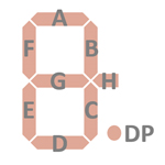
 Reverse-engineering
the SR-10 schematics reveals a simple trick used by Texas Instruments to control
its 12-digit display with only 11 digit outputs of the TMS0120: The unused "H"
segment available on the TMS0120 was repurposed for the minus sign of the
Exponent in the pictured (pictures on the left) way. Every time the "H" segment
output of the TMS0120 is activated, some additional circuitry on the PCB will
enable both the digit driver for the negative sign of the Exponent and the
segment driver for the "G" segment of Digit 3 (counted from right to
left) of the DIS115 Twelve-Digit display
module while the "G" segments of all other digits are activated by the "G"
segment output. Hence you'll find 21 connections between the Main-PCB and the
DIS115 Display-PCB:
Reverse-engineering
the SR-10 schematics reveals a simple trick used by Texas Instruments to control
its 12-digit display with only 11 digit outputs of the TMS0120: The unused "H"
segment available on the TMS0120 was repurposed for the minus sign of the
Exponent in the pictured (pictures on the left) way. Every time the "H" segment
output of the TMS0120 is activated, some additional circuitry on the PCB will
enable both the digit driver for the negative sign of the Exponent and the
segment driver for the "G" segment of Digit 3 (counted from right to
left) of the DIS115 Twelve-Digit display
module while the "G" segments of all other digits are activated by the "G"
segment output. Hence you'll find 21 connections between the Main-PCB and the
DIS115 Display-PCB:
|
• 12 connections for Digit 1 to Digit 12 • 1 connection for Segments G of Digit 3 • 1 connection for Segments G of Digit 1, Digit 2 and Digit 4 to Digit 12 • 6 connections for Segments A, B, C, D, E, and F of Digit 1 to Digit 12 • 1 connection for Decimal Point of Digit 1 to Digit 12 |
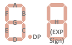
The first version of the SR-10 with two TIL360 Multi-Digit display modules used a slightly different approach, the "H" segment output of the TMS0120 enables both the digit driver for the negative sign of the Exponent and the segment driver for the "G" segments of the right TIL360 Multi-Digit display module while the "G" segments of the left TIL360 Multi-Digit display module are activated by the "G" segment output. Consequently the Main-PCB of the SR-10 was redesigned from Revision B to Revision D.
The featured SR-10 manufactured in March 1973 uses a DIS115F Twelve-Digit display module with 12 individual DISXXX Seven-Segment displays and an integrated magnifying lens.
![]()
![]() Display Driver: The Main-PCB of the featured SR-10 manufactured in
March 1973 makes use of a total of four Display Drivers. The two
SN27422 (SN75493) Segment Drivers for four segments, each and the two
SN27423 (SN75494) Digit Drivers for six digits, each are improvements of the original
SN75491/SN75492
chips introduced with the TMS1802 but allow for operation at lower voltages.
Display Driver: The Main-PCB of the featured SR-10 manufactured in
March 1973 makes use of a total of four Display Drivers. The two
SN27422 (SN75493) Segment Drivers for four segments, each and the two
SN27423 (SN75494) Digit Drivers for six digits, each are improvements of the original
SN75491/SN75492
chips introduced with the TMS1802 but allow for operation at lower voltages.
Clock: While the nominal clock frequency of the TMS0100 single-chip calculator circuit is specified with 250 kHz, uses the SR-10 a slower pace to reduce overall power consumption of the product slightly. The astable multivibrator using two discrete transistors operates at a frequency between 150 kHz and 200 kHz, we observed with the featured SR-10 manufactured in March 1973 a clock frequency of 185 kHz.
Texas Instruments introduced in August 1973 with the TI-2500 Version 3 the approach of a dynamic switching of the clock frequency for the TMS0100 single-chip calculator circuit to conserve power between calculations. The astable multivibrator idles at a frequency of around 50 kHz but increases with the detection of a depressed keybutton for a short time to about 200 kHz to reduce execution time of the operations. Two diodes are connected between the keymatrix inputs KN (numbers) and KO (operations) and the oscillator to catch every entry of a number or function keys for a impressive reduction of power consumption.
Power Supply: The SR-10 is powered by three AA-sized rechargeable NiCd batteries resulting in a typical voltage between 3.0 V (completely depleted cells) and 4.5 V (while charging full cells). The Main-PCB hosts a power converter circuit centered around an astable multivibrator, step-up transformer and various diodes and capacitors to generate the supply voltages for the TMS0120 chip and the clock oscillator. We observed in the featured SR-10 manufactured in March 1973 rather asymmetrical output voltages of VSS = 7.2 V and VGG = -8.0 V for the electronics.
Battery Saver Circuit: To save battery power the LED display turns off automatically between 15 and 60 seconds after the last keyboard entry, except for the first digit (Digit D3 of TMS0120, LSD of Mantissa). If the display turns off while entering a problem, the display turns on automatically with the first keyboard entry. Depressing the [=] key brings back the last calculated display. Three diodes are connected between the keymatrix inputs KN (numbers), KO (operations) and KP ([1/x], [x2] and [sqr X]) and a simple monoflop to catch every entry of a number or function keys to keep the Digit Drivers enabled. If the monoflop time expires, the Digit Drivers sans Digit 3 are disabled for an impressive reduction of power consumption:
| Mode | Display | Current VBAT = 4.5 V |
Clock Frequency |
| Calculating | 0 | 63 mA | 185 kHz |
| Power Save | 0 | 63 mA | 185 kHz |
| Calculating | E88888888-88 | 132 mA | 185 kHz |
| Power Save | 8 | 75 mA | 185 kHz |
Keyboard: The Klixon™ type keyboard looks very similar to the Datamath calculator with some additional keys placed in the upper line. Later calculators like the SR-11 changed the style of the keys but kept the extreme wedge-style of the housing that was adopted for the scientific desktop calculators SR-20 and SR-22, too. The last portable scientific calculator with this wedge-design was introduced in October 1974 with the SR-16.
![]() The first series of the SR-10
shared the poor readability
of the TIL360
based
display with the early Datamath calculators.
The first series of the SR-10
shared the poor readability
of the TIL360
based
display with the early Datamath calculators.
![]() Texas
Instruments experimented with different solutions and created some prototypes
with lenses attached to the 6-digit LED-modules.
Texas
Instruments experimented with different solutions and created some prototypes
with lenses attached to the 6-digit LED-modules.
Later models used different LED-modules with an additional magnification lens.
Don't miss the rare SR-10 Clear-Case Prototype and
compare it with the SR-10 Version 2.
 Not only the appearance of the SR-10 and the used LED-modules changed during the life cycle of the calculator, a later cost-reduction redesign changed the Main-PCB completely and we differentiate between
four different SR-10 Versions manufactured in the United States between November 1972 and
June 1975:
Not only the appearance of the SR-10 and the used LED-modules changed during the life cycle of the calculator, a later cost-reduction redesign changed the Main-PCB completely and we differentiate between
four different SR-10 Versions manufactured in the United States between November 1972 and
June 1975:
| Version | Position of SR-10 logo |
Display Type |
Display Driver |
| SR-10 USA V1 | Display frame | 6-digit modules without lens |
4 ICs |
| SR-10 USA V1D2 | Display frame | single modules with lens |
4 ICs |
| SR-10 USA V2 | Keyboard | single modules with lens |
4 ICs |
| SR-10 USA V3 | Keyboard | single modules with lens |
2 ICs |
Here at the Datamath Calculator Museum we classify the featured SR-10 as Display Frame Version 1, PCB Type 2 and Display Type 2.
The SR-10 manufactured in Italy for the European market introduced a slightly different design of the housing.
The SR-10 was sold with different nameplates, compare it with both the Radio Shack EC-425 and the Montgomery Ward P300.
Don't miss the TI-150, the only basic calculator using the silver trim around the display.
If you have additions to the above article please email: joerg@datamath.org.
© Joerg Woerner, November 18, 2021. No reprints without written permission.