DATAMATH CALCULATOR MUSEUM
|
|
DATAMATH CALCULATOR MUSEUM |
Characterization of General Instrument 250 / C-500 Product Family Single-chip Calculator Circuits
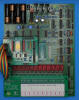
The DCM-50A (PLAYGROUND) supports the Characterization of the GI 250 / C-500 Product Family single-chip calculator circuits using the DCM-50A Playground C-500 Family Adapter mounted on top of the DCM-50A PG Frame Carrier and connected to the DCM50A Playground KBD102 Keyboard. The optional DCM-50A Playground Digilent I/O Extender supports Characterization and Reverse-engineering of GI 250 / C-500 Product Family single-chip calculator circuits.

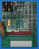
 Device-under-Test:
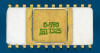
| • Package Markings Top:
250 GI 7211 • Package Markings Bottom: • Donor Calculator: Litton Royal Digital III, March 1972 |
Keyboard: The Litton Royal Digital III makes use 19 gold-plates squares/rectangles etched on its Main-PCB and a wired stylus with a metal tip to operate the calculator. The 19 key contacts are connected with series resistors to 19 pins of the GI 250 single-chip calculator circuit, while the stylus is driven with a pulsed output signal of the GI 250 and a transistor working as buffer (voltage follower).
Keyboard Matrix Litton Royal Digital III:
GI 250 |
||
| Pin# | KB_EN | |
| K0/SB | 12 | 0 |
| K1/SF | 9 | 1 |
| K2/SG | 10 | 2 |
| K3/SA | 11 | 3 |
| K4 | 5 | 4 |
| K5/SC | 8 | 5 |
| K6 | 4 | 6 |
| K7/SD | 7 | 7 |
| K8/SE | 6 | 8 |
| K9 | 3 | 9 |
| KP/SDP | 14 | . |
| KC | 20 | C |
| KK | 22 | K |
| KT | 21 | ↔ |
| KA/D48 | 17 | + |
| KS/D37 | 16 | − |
| KM/D26 | 18 | × |
| KD/D15B | 19 | ÷ |
| KEQ | 15 | = |
![]() Display:
The Litton Royal Digital III makes use of four low-voltage Vacuum Fluorescent
Display (VFD) tubes
manufactured by an unknown company and the grids connected with four additional
transistors to the
respective 4 Digit Outputs D15, D26, D37, and D48 of the GI 250. The anodes of
the segments are connected directly to the 8 Segment Outputs SA to SG and SDP of
the GI 250 and biased to approximately -25 Volts.
Display:
The Litton Royal Digital III makes use of four low-voltage Vacuum Fluorescent
Display (VFD) tubes
manufactured by an unknown company and the grids connected with four additional
transistors to the
respective 4 Digit Outputs D15, D26, D37, and D48 of the GI 250. The anodes of
the segments are connected directly to the 8 Segment Outputs SA to SG and SDP of
the GI 250 and biased to approximately -25 Volts.
Display Layout:
| Unknown VFD |
|
|
| The Segment drivers A-G and DP (Decimal Point) are connected to the unknown display in the pictured way. | 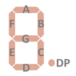 |
Display Fonts:
| Type | Calculator | Number Fonts | Decimal Separator |
Thousands Separator |
Entry Overflow |
Calculating Overflow |
Minus |
| GI 250 | Litton Royal Digital III |
|
n.a. |


 Keyboard Scanning:
The GI 250 uses a keyboard scanning matrix with all of its 19 keys connected
directly to a corresponding pin, while the common signal is connected to a
dedicated Keyboard Enable pin. Seven of the 19 keys are using dedicated Key
Input pins, four are shared with the Digit Outputs and eight are shared with the
Segment Outputs. To allow for the use of the Digit and Segment Output pins as
Key Input pins, the GI 250 is blanking the display completely before each
Display Scanning Cycle while reading the keyboard. Scanning the keyboard is
indicated with a short pulse on the Keyboard-Enable output pin while briefly
disabling all of its segments and digit output drivers before and after the
pulse.
Keyboard Scanning:
The GI 250 uses a keyboard scanning matrix with all of its 19 keys connected
directly to a corresponding pin, while the common signal is connected to a
dedicated Keyboard Enable pin. Seven of the 19 keys are using dedicated Key
Input pins, four are shared with the Digit Outputs and eight are shared with the
Segment Outputs. To allow for the use of the Digit and Segment Output pins as
Key Input pins, the GI 250 is blanking the display completely before each
Display Scanning Cycle while reading the keyboard. Scanning the keyboard is
indicated with a short pulse on the Keyboard-Enable output pin while briefly
disabling all of its segments and digit output drivers before and after the
pulse.


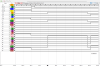
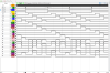
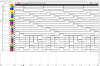
 Display
scanning: Display scanning is performed in is performed in D15 → D48
direction at a rate of about 830 Hz:
Display
scanning: Display scanning is performed in is performed in D15 → D48
direction at a rate of about 830 Hz:
|
• State Time = 2 Clocks = 0.020 ms @ CK=100 kHz • Keyboard Time = 8 States = 0.160 ms @ CK=100 kHz • Digit Time = 13 States = 0.260 ms @ CK=100 kHz • Scan Time = Keyboard Time + 4 Digit Times (D15 to D48) = 1.2 ms @ CK=100 kHz |
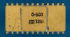
 Device-under-Test:
| • Package Markings Top:
251F GI 7213 • Package Markings Bottom: • Donor Calculator: Litton Royal Digital V, May 1972 |
Keyboard: The keyboard assembly of the Litton Royal Digital V uses 18 spring-supported plastic keys pushing fingers on a stamped sheet-metal piece against large, gold-plated contacts on the Main-PCB. The sheet-metal piece itself is connected through two additional contacts with the Main-PCB.
Keyboard Matrix Litton Royal Digital V:
GI 251F |
||
| Pin# | KB_EN | |
| K0/SB | 12 | 0 |
| K1/SF | 9 | 1 |
| K2/SG | 10 | 2 |
| K3/SA | 11 | 3 |
| K4 | 5 | 4 |
| K5/SC | 8 | 5 |
| K6 | 4 | 6 |
| K7/SD | 7 | 7 |
| K8/SE | 6 | 8 |
| K9 | 3 | 9 |
| KP/SDP | 14 | . |
| KC | 20 | C |
| KK | 22 | K |
| KA/D48 | 17 | + |
| KS/D37 | 16 | − |
| KM/D26 | 18 | × |
| KD/D15B | 19 | ÷ |
| KEQ | 15 | = |
![]() Display:
The Litton Royal Digital V makes use of an 8-Digit low-voltage Vacuum
Fluorescent Display (VFD) manufactured by Futaba and known as Type 8-CT-01,
soldered with its 19 pins directly to the Main-PCB. Both the 4 Digit Outputs
D15, D26, D37, and D48 and the 8 Segment Outputs SA to SG and SDP of the GI 251F
are inverted with two Mitsubishi M58212 chips and connected through a bank of 18
discrete transistors to the . Eight inverting transistors are used for the D1 to
D8 VFD grids, with two extra, non-inverting transistors selecting the upper or
lower digit group of the GI 251F. Eight inverting transistors are used for the A
to G and DP VFD anodes, biased to around -44 Volts.
Display:
The Litton Royal Digital V makes use of an 8-Digit low-voltage Vacuum
Fluorescent Display (VFD) manufactured by Futaba and known as Type 8-CT-01,
soldered with its 19 pins directly to the Main-PCB. Both the 4 Digit Outputs
D15, D26, D37, and D48 and the 8 Segment Outputs SA to SG and SDP of the GI 251F
are inverted with two Mitsubishi M58212 chips and connected through a bank of 18
discrete transistors to the . Eight inverting transistors are used for the D1 to
D8 VFD grids, with two extra, non-inverting transistors selecting the upper or
lower digit group of the GI 251F. Eight inverting transistors are used for the A
to G and DP VFD anodes, biased to around -44 Volts.
Display Layout:
| Futaba 8-CT-01 |
|
|
| The Segment drivers A-G and DP (Decimal Point) are connected to the Futaba 8-CT-01 display in the pictured way. Segment H is not used. | 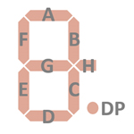 |
Display Fonts:
| Type | Calculator | Number Fonts | Decimal Separator |
Thousands Separator |
Entry Overflow |
Calculating Overflow |
Minus |
| GI 251F | Litton Royal Digital V |
|
n.a. |
 Keyboard Scanning:
The GI 251F uses a keyboard scanning matrix with all of its 18 keys connected
directly to a corresponding pin, while the common signal is connected to a
dedicated Keyboard Enable pin. Seven of the 18 keys are using dedicated Key
Input pins, four are shared with the Digit Outputs and eight are shared with the
Segment Outputs. To allow for the use of the Digit and Segment Output pins as
Key Input pins, the GI 251F is blanking the display completely before and in the
middle of each
Display Scanning Cycle while reading the keyboard. Scanning the keyboard is
indicated with a short pulse on the Keyboard-Enable output pin while briefly
disabling all of its segments and digit output drivers before and after the
pulse.
Keyboard Scanning:
The GI 251F uses a keyboard scanning matrix with all of its 18 keys connected
directly to a corresponding pin, while the common signal is connected to a
dedicated Keyboard Enable pin. Seven of the 18 keys are using dedicated Key
Input pins, four are shared with the Digit Outputs and eight are shared with the
Segment Outputs. To allow for the use of the Digit and Segment Output pins as
Key Input pins, the GI 251F is blanking the display completely before and in the
middle of each
Display Scanning Cycle while reading the keyboard. Scanning the keyboard is
indicated with a short pulse on the Keyboard-Enable output pin while briefly
disabling all of its segments and digit output drivers before and after the
pulse.
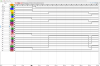
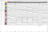
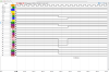
 Display
scanning: Display scanning is performed in is performed in two 4-digit
groups in D15 → D48 direction at a rate of about 420 Hz:
Display
scanning: Display scanning is performed in is performed in two 4-digit
groups in D15 → D48 direction at a rate of about 420 Hz:
|
• State Time = 2 Clocks = 0.020 ms @ CK=100 kHz • Keyboard Time = 8 States = 0.160 ms @ CK=100 kHz • Digit Time = 13 States = 0.260 ms @ CK=100 kHz • Scan Time = Keyboard Time + 4 Digit Times (D15 to D48) + Keyboard Time + 4 Digit Times (D15 to D48) = 2.4 ms @ CK=100 kHz |
 Device-under-Test:
| • Package Markings Top:
C-500 GI 7251 • Package Markings Bottom: • Donor Calculator: Litton Royal RC 80, January 1973 |
Keyboard: The keyboard assembly of the Litton Royal RC 80 uses 18 spring-supported plastic keys pushing fingers on a stamped sheet-metal piece against large, gold-plated contacts on the Main-PCB. The sheet-metal piece itself is connected through two additional contacts with the Main-PCB.
Keyboard Matrix Litton Royal RC 80:
C-500 |
||
| Pin# | KB_EN | |
| K0/SB | 12 | 0 |
| K1/SF | 9 | 1 |
| K2/SG | 10 | 2 |
| K3/SA | 11 | 3 |
| K4 | 5 | 4 |
| K5/SC | 8 | 5 |
| K6 | 4 | 6 |
| K7/SD | 7 | 7 |
| K8/SE | 6 | 8 |
| K9 | 3 | 9 |
| KP/SDP | 14 | . |
| KC | 20 | C |
| KK | 22 | K |
| KA/D48 | 17 | + |
| KS/D37 | 16 | − |
| KM/D26 | 18 | × |
| KD/D15B | 19 | ÷ |
| KEQ | 15 | = |
![]() Display:
The Litton Royal RC 80 makes use of an 8-Digit low-voltage Vacuum
Fluorescent Display (VFD) manufactured by Futaba and known as Type 8-CT-01A,
soldered with its 19 pins directly to the Main-PCB. Both the 4 Digit Outputs
D15, D26, D37, and D48 and the 8 Segment Outputs SA to SG and SDP of the C-500
are inverted with two Mitsubishi M58212 chips and connected through a bank of 18
discrete transistors to the . Eight inverting transistors are used for the D1 to
D8 VFD grids, with two extra, non-inverting transistors selecting the upper or
lower digit group of the C-500. Eight inverting transistors are used for the A
to G and DP VFD anodes, biased to around -44 Volts.
Display:
The Litton Royal RC 80 makes use of an 8-Digit low-voltage Vacuum
Fluorescent Display (VFD) manufactured by Futaba and known as Type 8-CT-01A,
soldered with its 19 pins directly to the Main-PCB. Both the 4 Digit Outputs
D15, D26, D37, and D48 and the 8 Segment Outputs SA to SG and SDP of the C-500
are inverted with two Mitsubishi M58212 chips and connected through a bank of 18
discrete transistors to the . Eight inverting transistors are used for the D1 to
D8 VFD grids, with two extra, non-inverting transistors selecting the upper or
lower digit group of the C-500. Eight inverting transistors are used for the A
to G and DP VFD anodes, biased to around -44 Volts.
Display Layout:
| Futaba 8-CT-01A |
|
|
| The Segment drivers A-G and DP (Decimal Point) are connected to the Futaba 8-CT-01A display in the pictured way. Segment H is not used. | |
Display Fonts:
| Type | Calculator | Number Fonts | Decimal Separator |
Thousands Separator |
Entry Overflow |
Calculating Overflow |
Minus |
| C-500 | Litton Royal RC 80 |
|
n.a. |
Keyboard Scanning:
The C-500 uses a keyboard scanning matrix with all of its 18 keys connected
directly to a corresponding pin, while the common signal is connected to a
dedicated Keyboard Enable pin. Seven of the 18 keys are using dedicated Key
Input pins, four are shared with the Digit Outputs and eight are shared with the
Segment Outputs. To allow for the use of the Digit and Segment Output pins as
Key Input pins, the C-500 is blanking the display completely before and in the
middle of each
Display Scanning Cycle while reading the keyboard. Scanning the keyboard is
indicated with a short pulse on the Keyboard-Enable output pin while briefly
disabling all of its segments and digit output drivers before and after the
pulse.
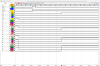
 Display
scanning: Display scanning is performed in is performed in two 4-digit
groups in D15 → D48 direction at a rate of about 420 Hz:
Display
scanning: Display scanning is performed in is performed in two 4-digit
groups in D15 → D48 direction at a rate of about 420 Hz:
|
• State Time = 2 Clocks = 0.020 ms @ CK=100 kHz • Keyboard Time = 8 States = 0.160 ms @ CK=100 kHz • Digit Time = 13 States = 0.260 ms @ CK=100 kHz • Scan Time = Keyboard Time + 4 Digit Times (D15 to D48) + Keyboard Time + 4 Digit Times (D15 to D48) = 2.4 ms @ CK=100 kHz |
 Device-under-Test:
| • Package Markings Top:
C-550 GI 7324 • Package Markings Bottom: • Donor Calculator: Interton PC 2008 (Version 2), July 1973 |
Keyboard: The Litton Interton PC 2008 makes use 19 gold-plated snap action switches mounted directly on a second PCB of the calculator together with a sliding switch for power. The [C] and [CE] keys are hardwired on the Keyboard-PCB together and act as a single [C] key.
Keyboard Matrix Interton PC 2008 (Version 2):
C-550 |
||
| Pin# | KB_EN | |
| K0/SB | 12 | 0 |
| K1/SF | 9 | 1 |
| K2/SG | 10 | 2 |
| K3/SA | 11 | 3 |
| K4 | 5 | 4 |
| K5/SC | 8 | 5 |
| K6 | 4 | 6 |
| K7/SD | 7 | 7 |
| K8/SE | 6 | 8 |
| K9 | 3 | 9 |
| KP/SDP | 14 | . |
| KC | 20 | C, CE |
| KK | 22 | K |
| KA/D48 | 17 | + |
| KS/D37 | 16 | − |
| KM/D26 | 18 | × |
| KD/D15B | 19 | ÷ |
| KEQ | 15 | = |
![]() Display:
The Interton PC 2008 (Version 2) makes use of Bowmar Nine-Digit Calculator Numeric
Seven-Segment LED Optostik Display module, very similar to the type R7H-112-9.
It uses seven individual GaAsP (Gallium Arsenide Phosphide) Segment LED
chips and one GaAsP Decimal Point LED chip per character bonded directly to
a double-sided FR4 printed circuit board (PCB) and placing a one-piece red
acrylic protecting lens on top of the assembly with four heat stakes. The
leftmost display position is missing like the R7H-112-9 the upper right segment,
but sports the decimal point. The display module is connected with 17 pins
to the Main-PCB of the calculator, but the left most pin (Digit D9 Common
Cathode) is not used. Two ITT 491 (SN75491-style) "Segment
Drivers" with four channels, each are connected to the D15, D26, D37, and D48 digit outputs of the
C-550 chip with two additional transistors connected to the UD_EN and
LD_EN outputs of the C-550, selecting the upper or lower digit groups of the
ITT 491 drivers. The outputs of the two ITT 491 drivers are connected to the
Common Cathodes D1 to D8 of the LED display. The A to G segments (Anodes) of the
LED display are driven with a CA3082 transistor array while the Decimal Point
(Anode) is driven by a discrete transisistor.
Display:
The Interton PC 2008 (Version 2) makes use of Bowmar Nine-Digit Calculator Numeric
Seven-Segment LED Optostik Display module, very similar to the type R7H-112-9.
It uses seven individual GaAsP (Gallium Arsenide Phosphide) Segment LED
chips and one GaAsP Decimal Point LED chip per character bonded directly to
a double-sided FR4 printed circuit board (PCB) and placing a one-piece red
acrylic protecting lens on top of the assembly with four heat stakes. The
leftmost display position is missing like the R7H-112-9 the upper right segment,
but sports the decimal point. The display module is connected with 17 pins
to the Main-PCB of the calculator, but the left most pin (Digit D9 Common
Cathode) is not used. Two ITT 491 (SN75491-style) "Segment
Drivers" with four channels, each are connected to the D15, D26, D37, and D48 digit outputs of the
C-550 chip with two additional transistors connected to the UD_EN and
LD_EN outputs of the C-550, selecting the upper or lower digit groups of the
ITT 491 drivers. The outputs of the two ITT 491 drivers are connected to the
Common Cathodes D1 to D8 of the LED display. The A to G segments (Anodes) of the
LED display are driven with a CA3082 transistor array while the Decimal Point
(Anode) is driven by a discrete transisistor.
Display Layout:
| Nine-Digit LED Module Bowmar Optostik |
|
|
| The Segment drivers A-G and DP (Decimal Point) are connected to the Bowmar Optostik display in the pictured way. | |
Display Fonts:
| Type | Calculator | Number Fonts | Decimal Separator |
Thousands Separator |
Entry Overflow |
Calculating Overflow |
Minus |
| C-550 | Interton PC 2008 |
|
n.a. |
Keyboard Scanning:
The C-550 uses a keyboard scanning matrix with all of its 18 keys connected
directly to a corresponding pin, while the common signal is connected to a
dedicated Keyboard Enable pin. Seven of the 18 keys are using dedicated Key
Input pins, four are shared with the Digit Outputs and eight are shared with the
Segment Outputs. To allow for the use of the Digit and Segment Output pins as
Key Input pins, the C-550 is blanking the display completely before and in the
middle of each
Display Scanning Cycle while reading the keyboard. Scanning the keyboard is
indicated with a short pulse on the Keyboard-Enable output pin while briefly
disabling all of its segments and digit output drivers before and after the
pulse.
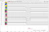
 Display
scanning: Display scanning is performed in is performed in two 4-digit
groups in D15 → D48 direction at a rate of about 420 Hz:
Display
scanning: Display scanning is performed in is performed in two 4-digit
groups in D15 → D48 direction at a rate of about 420 Hz:
|
• State Time = 2 Clocks = 0.020 ms @ CK=100 kHz • Keyboard Time = 8 States = 0.160 ms @ CK=100 kHz • Digit Time = 13 States = 0.260 ms @ CK=100 kHz • Scan Time = Keyboard Time + 4 Digit Times (D15 to D48) + Keyboard Time + 4 Digit Times (D15 to D48) = 2.4 ms @ CK=100 kHz |
 Device-under-Test:
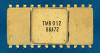
| • Package Markings Top:
TMR 012 B8472 • Package Markings Bottom: • Donor Calculator: Interton PC 2008 (Version 1), January 1973 |
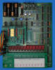
Keyboard: The Litton Interton PC 2008 makes use 19 gold-plated snap action switches mounted directly on a second PCB of the calculator together with a sliding switch for power. The [C] and [CE] keys are hardwired on the Keyboard-PCB together and act as a single [C] key.
Keyboard Matrix Interton PC 2008 (Version 1):
TMR 012 |
||
| Pin# | KB_EN | |
| K0/SB | 12 | 0 |
| K1/SF | 9 | 1 |
| K2/SG | 10 | 2 |
| K3/SA | 11 | 3 |
| K4 | 5 | 4 |
| K5/SC | 8 | 5 |
| K6 | 4 | 6 |
| K7/SD | 7 | 7 |
| K8/SE | 6 | 8 |
| K9 | 3 | 9 |
| KP/SDP | 14 | . |
| KC | 20 | C, CE |
| KK | 22 | K |
| KA/D48 | 17 | + |
| KS/D37 | 16 | − |
| KM/D26 | 18 | × |
| KD/D15B | 19 | ÷ |
| KEQ | 15 | = |
![]() Display:
The Interton PC 2008 (Version 1) makes use of Bowmar Nine-Digit Calculator Numeric
Seven-Segment LED Optostik Display module, very similar to the type R7H-112-9.
It uses seven individual GaAsP (Gallium Arsenide Phosphide) Segment LED
chips and one GaAsP Decimal Point LED chip per character bonded directly to
a double-sided FR4 printed circuit board (PCB) and placing a one-piece red
acrylic protecting lens on top of the assembly with four heat stakes. The
leftmost display position is missing like the R7H-112-9 the upper right segment,
but sports the decimal point. The display module is connected with 17 pins
to the Main-PCB of the calculator, but the left most pin (Digit D9 Common
Cathode) is not used. Two
SN75491 "Segment
Drivers" with four channels, each are connected to the D15, D26, D37, and D48 digit outputs of the
TMR 012 chip with two additional transistors connected to the UD_EN and
LD_EN outputs of the TMR 012, selecting the upper or lower digit groups of the
SN75491 drivers. The outputs of the two SN75491 drivers are connected to the
Common Cathodes D1 to D8 of the LED display. The A to G segments (Anodes) of the
LED display are driven with a CA3082 transistor array while the Decimal Point
(Anode) is driven by a discrete transisistor.
Display:
The Interton PC 2008 (Version 1) makes use of Bowmar Nine-Digit Calculator Numeric
Seven-Segment LED Optostik Display module, very similar to the type R7H-112-9.
It uses seven individual GaAsP (Gallium Arsenide Phosphide) Segment LED
chips and one GaAsP Decimal Point LED chip per character bonded directly to
a double-sided FR4 printed circuit board (PCB) and placing a one-piece red
acrylic protecting lens on top of the assembly with four heat stakes. The
leftmost display position is missing like the R7H-112-9 the upper right segment,
but sports the decimal point. The display module is connected with 17 pins
to the Main-PCB of the calculator, but the left most pin (Digit D9 Common
Cathode) is not used. Two
SN75491 "Segment
Drivers" with four channels, each are connected to the D15, D26, D37, and D48 digit outputs of the
TMR 012 chip with two additional transistors connected to the UD_EN and
LD_EN outputs of the TMR 012, selecting the upper or lower digit groups of the
SN75491 drivers. The outputs of the two SN75491 drivers are connected to the
Common Cathodes D1 to D8 of the LED display. The A to G segments (Anodes) of the
LED display are driven with a CA3082 transistor array while the Decimal Point
(Anode) is driven by a discrete transisistor.
Display Layout:
| Nine-Digit LED Module Bowmar Optostik |
|
|
| The Segment drivers A-G and DP (Decimal Point) are connected to the Bowmar Optostik display in the pictured way. | |
Display Fonts:
| Type | Calculator | Number Fonts | Decimal Separator |
Thousands Separator |
Entry Overflow |
Calculating Overflow |
Minus |
| TMR 012 | Interton PC 2008 |
|
n.a. |
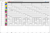
Keyboard Scanning:
The TMR 012 uses a keyboard scanning matrix with all of its 18 keys connected
directly to a corresponding pin, while the common signal is connected to a
dedicated Keyboard Enable pin. Seven of the 18 keys are using dedicated Key
Input pins, four are shared with the Digit Outputs and eight are shared with the
Segment Outputs. To allow for the use of the Digit and Segment Output pins as
Key Input pins, the TMR 012 is blanking the display completely before and in the
middle of each
Display Scanning Cycle while reading the keyboard. Scanning the keyboard is
indicated with a short pulse on the Keyboard-Enable output pin while briefly
disabling all of its segments and digit output drivers before and after the
pulse.
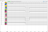
 Display
scanning: Display scanning is performed in is performed in two 4-digit
groups in D15 → D48 direction at a rate of about 420 Hz:
Display
scanning: Display scanning is performed in is performed in two 4-digit
groups in D15 → D48 direction at a rate of about 420 Hz:
|
• State Time = 2 Clocks = 0.020 ms @ CK=100 kHz • Keyboard Time = 8 States = 0.160 ms @ CK=100 kHz • Digit Time = 13 States = 0.260 ms @ CK=100 kHz • Scan Time = Keyboard Time + 4 Digit Times (D15 to D48) + Keyboard Time + 4 Digit Times (D15 to D48) = 2.4 ms @ CK=100 kHz |
If you have additions to the above article please email: joerg@datamath.org.
© Joerg Woerner, July 8, 2025. No reprints without written permission.