DATAMATH CALCULATOR MUSEUM
|
DATAMATH CALCULATOR MUSEUM |
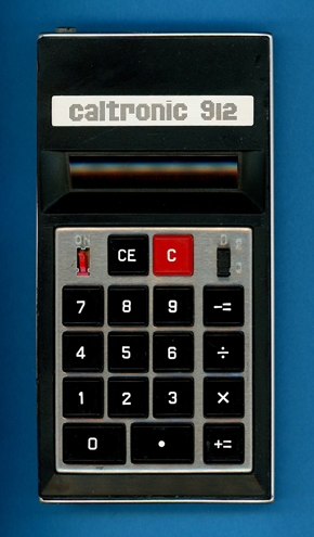
Caltronic Model 912
| Date of introduction: | January 1973 | Display technology: | LED modules |
| New price: | Display size: | 8 + Sign | |
| Size: | 5.8" x 3.0" x 0.9" 148 x 77 x 23 mm3 |
||
| Weight: | 6.1 ounces, 173 grams | Serial No: | 172388 |
| Batteries: | 9V Alkaline | Date of manufacture: | mth 02 year 1973 |
| AC-Adapter: | Origin of manufacture: | Hong Kong | |
| Precision: | 8 (12) | Integrated circuits: | MK5012 |
| Logic: | Adding Machine | Displays: | 3*Litronix DL-33 |
| Memories: | |||
| Program steps: | Courtesy of: | Joerg Woerner |
 Harber Industries Limited in Hong Kong entered the calculator business in 1972 with the Caltronic
812 and soon offered its product line as white-label products to OEMs (Original Equipment Manufacturer) like
Quelle and
Neckermann in Germany and UK-based Plustronics Ltd. Although total sales approached one million calculators in 1973, the business was not sustainable for the contract manufacturer, Coltronics, a subsidiary of Cable
& Wireless Ltd. in Hong Kong, which discontinued calculator production in 1974.
Harber Industries Limited in Hong Kong entered the calculator business in 1972 with the Caltronic
812 and soon offered its product line as white-label products to OEMs (Original Equipment Manufacturer) like
Quelle and
Neckermann in Germany and UK-based Plustronics Ltd. Although total sales approached one million calculators in 1973, the business was not sustainable for the contract manufacturer, Coltronics, a subsidiary of Cable
& Wireless Ltd. in Hong Kong, which discontinued calculator production in 1974.
As implied by its model number, 812, the Caltronic 812 is built around a calculator chip with 12-digit internal precision but an 8-digit LED display. The discrepancy between internal precision and visible output results in several surprising operating characteristics (Examples shown with Decimal Point switch set to [0 2]:
|
• Entering the 9th digit is resulting in the two left most
decimal points lit up: [1] [2] [3] [4] [5] [6] [7] [8] [9] → 2.3.456789 • Entering the 13th digit is resulting in an overflow with all zeroes and seven decimal points: → 0.0.0 0.0.0.0.0. • Calculations with 9 to 12 digits are shown with the three decimal points lit up: [1] [2] [3] [4] [5] [x] [1] [2] [3] [4] [5] [+=] → 5.2.399025. and allowing further calculations: [:] [1] [0] [0] [+=] → 1523990. • Calculations with more than 12 digits are resulting in an overflow with all zeroes and seven decimal points: [1] [2] [3] [4] [5] [x] [1] [2] [3] [4] [5] [x] [1] [2] [3] [4] [5] [+=] → 0.0.0 0.0.0.0.0. |
Introduced in September 1972, at the dawn of the Calculator War, the Caltronic 812 came under intense cost-reduction pressure. As a result, Coltronics implemented numerous design and manufacturing changes throughout the calculator's production life:
|
• Substitution of two segment driver chips with resistors • Elimination of the connector between the Main-PCB and the keyboard/display assembly • Redesign of the internal construction of the calculator, resulting in a smaller housing • Switching the PCB substrate from fiberglass-reinforced epoxy laminate to phenolic laminate • Replacing the Cal-Tex calculator chip with a product from Mostek |
In addition, Caltronic introduced with the Models 606 and 612 two variations using 6-digit display and replacing the Texas Instruments Klixon keyboards to further reduce manufacturing costs.
We acquired this Caltronic 912 calculator together with three other calculators on our quest to untangle the relationships between the MK6010L, MK5012, MK5010, and Cal-Tex CT5002 single-chip calculator circuits. Each calculator went through our "Teardown Treatment", Characterization of Single-Chip Calculator Circuits and De-capping and Chip-Photography:
|
• MK6010L - Busicom
LE-120S,
Teardown,
Characterization,
Die Photo • MK5012 - Caltronic 912, Teardown, Characterization, Die Photo • MK5010 - Rapid Data Rapidman 800, Teardown, Characterization, Die Photo • CT5002 - Caltronic 812, Teardown, Characterization, Die Photo |
In addition did we acquire multiple Caltronic calculators and their OEM products manufactured for Neckermann and Quelle (Privileg brand) to understand the various cost-reduction measures and hoping to discover the rumored Cal-Tex CT5012 chip.
Using the Mostek MK5012 calculator brain instead of the Cal-Tex CT5002 used in the original Caltronic 812 results in minor changes to the calculator's overflow indication:
|
• Caltronic 812 Calculating Overflow - '0.0.0 0.0.0.0.0.' • Caltronic 812 Calculating Overflow - '0.0.0.0.0.0.0.0.' |


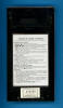 Dismantling
the featured Caltronic 912 calculator manufactured in February 1973 in Hong Kong reveals a
completely revised internal construction compared with the original Caltronic
812, replacing the connector between its Main-PCB, the
Display-PCB and the Keyboard Assembly with short wires:
Dismantling
the featured Caltronic 912 calculator manufactured in February 1973 in Hong Kong reveals a
completely revised internal construction compared with the original Caltronic
812, replacing the connector between its Main-PCB, the
Display-PCB and the Keyboard Assembly with short wires:
|
• Main-PCB - Mostek MK5012 single-chip calculator circuit, display driver,
keyboard encoding and power supply • Display-PCB - Three Litronix 3-digit 7-segment LED display modules and one indicator LED • Keyboard Assembly - Texas Instruments Klixon™ keyboard array |

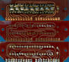
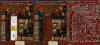 To
gain some knowledge about the differences between the MK5012 located in this Caltronic
912 and the Cal-Tex CT5002 used with the Caltronic
812, we
decided here at the Datamath Calculator Museum to give it a "Teardown
Treatment" and sharing our findings accordingly.
To
gain some knowledge about the differences between the MK5012 located in this Caltronic
912 and the Cal-Tex CT5002 used with the Caltronic
812, we
decided here at the Datamath Calculator Museum to give it a "Teardown
Treatment" and sharing our findings accordingly.
 Calculating Unit: When Mostek introduced in November 1970 with the
MK6010 the World’s first "single-chip calculator circuit", it was sold exclusively to Nippon Calculating Machine Corp of Japan for their Busicom Model 120-DM small desktop calculator, also known as Busicom
Junior, and not available to other customers. Busicom recognized the potential of Mostek's ion-implantation process, which led to the introduction of the low-voltage, low-power
MK6010L in February 1971. The first application of the MK6010L was a remarkably compact, battery-operated handheld calculator with LED displays - quite the opposite of the original MK6010, which had been designed for a large, AC-powered desktop calculator with a VFD. Although Busicom succeeded in squeezing the required DC/DC converter and LED drivers into an exceptionally compact housing, the manufacturing costs of the
LE-120A and its successor, the
LE-120S, remained prohibitively high
and the company started early in 1972 to struggle financially. Busicom decided to forfeit its right of exclusivity, resulting in Mostek rebranding the MK6010 to MK5011 and its low power sibling MK6010L to MK5012.
Calculating Unit: When Mostek introduced in November 1970 with the
MK6010 the World’s first "single-chip calculator circuit", it was sold exclusively to Nippon Calculating Machine Corp of Japan for their Busicom Model 120-DM small desktop calculator, also known as Busicom
Junior, and not available to other customers. Busicom recognized the potential of Mostek's ion-implantation process, which led to the introduction of the low-voltage, low-power
MK6010L in February 1971. The first application of the MK6010L was a remarkably compact, battery-operated handheld calculator with LED displays - quite the opposite of the original MK6010, which had been designed for a large, AC-powered desktop calculator with a VFD. Although Busicom succeeded in squeezing the required DC/DC converter and LED drivers into an exceptionally compact housing, the manufacturing costs of the
LE-120A and its successor, the
LE-120S, remained prohibitively high
and the company started early in 1972 to struggle financially. Busicom decided to forfeit its right of exclusivity, resulting in Mostek rebranding the MK6010 to MK5011 and its low power sibling MK6010L to MK5012.
 Display:
The featured Caltronic 912 calculator, manufactured in February 1973, utilizes a
9-digit LED display assembly composed of three Litronix DL-33 3-digit seven-segment LED displays housed in
12-pin packages and soldered onto
the double-sided Display-PCB. In addition to the numeric displays, the Display-PCB incorporates
an indicator LEDs for low-battery status. The
Display-PCB is connected to the Main-PCB of the Caltronic 9812 with 21 hand-soldered
short wires.
Display:
The featured Caltronic 912 calculator, manufactured in February 1973, utilizes a
9-digit LED display assembly composed of three Litronix DL-33 3-digit seven-segment LED displays housed in
12-pin packages and soldered onto
the double-sided Display-PCB. In addition to the numeric displays, the Display-PCB incorporates
an indicator LEDs for low-battery status. The
Display-PCB is connected to the Main-PCB of the Caltronic 9812 with 21 hand-soldered
short wires.
Display Driver: The MK5012 single-chip calculator circuit and its
companion, the MK6010L, originated from the architecture of the Busicom Model 120-DM desktop calculator, better known as the Busicom
Junior. This calculator was built from 22 JMOS integrated circuits and featured
low-voltage vacuum fluorescent displays (VFDs). To facilitate display
interfacing, the designers chose a negative-logic configuration for the digit
and segment outputs, enabling straightforward drive circuitry based on discrete
transistors. This design philosophy was carried over to the MK6010 and MK6010L.
Consequently, both devices provide negative-logic digit and segment outputs,
requiring PNP bipolar junction transistors (BJTs) to drive the anodes and
cathodes of the 9-digit LED display. The necessary discrete transistors are
arranged on the Main-PCB of the Caltronic 912 calculator.
Clock: The MK5012 single-chip calculator circuit used in the Caltronic 912 operates from a two-phase clock running at approximately 20 to 25 kHz. The clock signal is generated by an astable multivibrator
consisting of four BJTs, which is located on the calculator's Main-PCB.
Power Supply: The Caltronic 912 calculator is powered by a
disposable 9 V alkaline battery. A switched-capacitor DC/DC converters generates
an additional supply voltage required by the MK5012 calculator chip:
|
• VSS - Positive supply for MK5012 (9.0 V) from battery • VDD - Negative supply for MK5012 (0 V) and LED display from battery • VGG - Negative supply for MK5012 (-5.0 V) from DC/DC converter |
We measured the operating current of the featured Caltronic 912 calculator for four different cases:
| Mode | Display | Current VBAT = 9.0 V |
Clock Frequency |
| Calculating | 0. | 39 mA | 22 kHz |
| Calculating | - 0. | 39 mA | 22 kHz |
| Calculating | 88888888 | 55 mA | 22 kHz |
| Display Hold | H. | 28 mA | 22 kHz |
Calculating the power consumption at 9 Volts for the Caltronic 912 results in about 350 mW displaying a '0.' and about 500 mW with all segments illuminated, rather disappointing high numbers for an LED-based calculator designed in 1972. An earlier Caltronic 812, based on Cal-Tex' CT5002, clocked in at 120 mW and 250 mW, respectively - clearly demonstrating the optimization of the CT5002 for LED-based, battery-operated calculators.
Keyboard: The Caltronic 912 uses a
Klixon™ 1KS116
keyboard assembly consisting of the "Basic 1KS" keyboard array with 17
snap-action Klixon discs mounted on a printed circuit board for the interconnections of the
switches to
the external calculator circuit and a stainless steel mounting frame and the
molded keytops. In addition, the keyboard assembly integrates two two-position slide switches: one for selecting the decimal-point position and the other for switching the calculator power on and off.
The keyboard assembly is connected to the Main-PCB of the Caltronic 912 with 22
hand-soldered short wires.
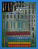 Here
at the Datamath Calculator Museum we use
the DCM-50A Platform to
Characterize and
Reverse-engineer
Single-chip Calculator Circuits. Many designs of electronic calculators do not
use all features of their calculator brains and it would be difficult to unleash
the full potential of the calculator chips in these cases. Additionally are
electronic calculators "closed systems" with limited flexibility to measure
signals, change voltages or clock frequencies, provide additional input keys or
even change the display technology or specifications additional digits. Core
idea of the DCM-50A is providing a generic platform to access all features of a
single-chip calculator circuit and with the
DCM-50A (PLAYGROUND) we
increased the scope from Texas Instruments products to offerings from their
competitors in the 1970s, namely AMI, Cal-Tex, Commodore/MOS Technology,
Electronic Arrays, General Instrument, Hitachi, Litronix, Matsushita,
Mitsubishi, Mostek, National Semiconductor, NEC, Omron, RFT, Rockwell, Sharp,
Toshiba, and Western Digital.
Here
at the Datamath Calculator Museum we use
the DCM-50A Platform to
Characterize and
Reverse-engineer
Single-chip Calculator Circuits. Many designs of electronic calculators do not
use all features of their calculator brains and it would be difficult to unleash
the full potential of the calculator chips in these cases. Additionally are
electronic calculators "closed systems" with limited flexibility to measure
signals, change voltages or clock frequencies, provide additional input keys or
even change the display technology or specifications additional digits. Core
idea of the DCM-50A is providing a generic platform to access all features of a
single-chip calculator circuit and with the
DCM-50A (PLAYGROUND) we
increased the scope from Texas Instruments products to offerings from their
competitors in the 1970s, namely AMI, Cal-Tex, Commodore/MOS Technology,
Electronic Arrays, General Instrument, Hitachi, Litronix, Matsushita,
Mitsubishi, Mostek, National Semiconductor, NEC, Omron, RFT, Rockwell, Sharp,
Toshiba, and Western Digital.
On our quest to document Mostek's MK6010 Chip and its
many descendants like the MK5010, MK5011, MK5012 and Cal-Tex' CT5001, CT5002, and
CT5012, we developed here at the Datamath Calculator Museum three additional
tools for our DCM-50A (PLAYGROUND):
| •
DCM-50A
(PLAYGROUND) MK6010 Adapter: Daughter Board for the
DCM-50A (PLAYGROUND)
Digit Inverter Frame Carrier for
Mostek's MK6010 Product Family • DCM-50A (PLAYGROUND) KBD102 Keyboard: Keyboard with 20 individual keys to support the MK6010-style BCD-Encoding keyboard input • DCM-50A (PLAYGROUND) Digilent I/O Extender: Plug-In Board to add six additional Input Signals for the Digilent Discovery |
Comparing the Calculator Logic Implementation of the MK5012 chip used with the featured Caltronic 912 calculator with the Calculator Logic Implementation of the CT5002 retrieved from a Caltronic 812 calculator reveals only subtle differences: An Entry or Calculating Overflow is signaled with the MK5012 showing '0.0.0.0.0.0.0.0.0.0.0.0', while the CT5002 is showing '00000000.0.0.0.0.'. Pressing the [C] or [CE] key lit up the display with all 12 digits showing '888888888888' with the MK5012, while the CT5002 is showing '000000000000'.
 In
a next step, we decided to "decap" the
CT5002 and MK5012 chips salvaged from the Caltonic
812 and Caltronic 912
calculators and asked Sean Riddle to
provide us with high-resolution images of the silicon dies.
In
a next step, we decided to "decap" the
CT5002 and MK5012 chips salvaged from the Caltonic
812 and Caltronic 912
calculators and asked Sean Riddle to
provide us with high-resolution images of the silicon dies.
First surprise: The silicon die inside the MK5012 package is
marked with MK6015 and bears the NCM logo.
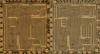 Second
surprise: The MK6015 (MK6010L/MK5012) chip looks almost identical to the CT5002 chip.
Second
surprise: The MK6015 (MK6010L/MK5012) chip looks almost identical to the CT5002 chip.

If you have additions to the above article please email: joerg@datamath.org.
© Joerg Woerner, July 4, 2026. No reprints without written permission.