DATAMATH CALCULATOR MUSEUM
|
DATAMATH CALCULATOR MUSEUM |
Centurion International Industries Multiputer (CPD-15)
| Date of introduction: | 1973 | Display technology: | LED |
| New price: | Display size: | 1+1+2 | |
| Size: | 10.6" x 10.6" x
12.8" 268 x 268 x 325 mm3 |
||
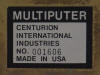
| Weight: | 90.0 ounces, 2,550 grams | Serial No: | 001606 |
| Batteries: | n.a. | Date of manufacture: | mth 11 year 1973 |
| AC-Adapter: | 120 V | Origin of manufacture: | USA |
| Precision: | Integrated circuits: | Fairchild 3805, 3806 (SL30342), 3807, 3809, 3810 (SL30745), 3811 | |
| Logic: | Displays: | 4*Litronix DL707 | |
| Memories: | |||
| Program steps: | Courtesy of: | Jeri Ellsworth |
![]()
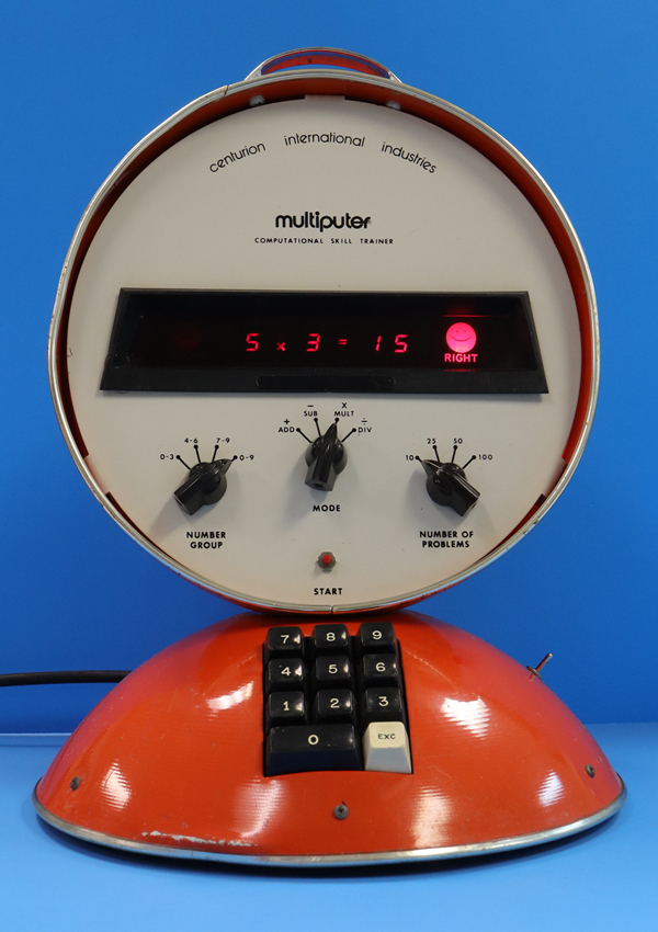
 With the introduction of the first microprocessors in the early 1970s, American inventor and electrical engineer John P. Cline developed a device called Multiputer
Computational Skill Trainer to drill children in arithmetic. Similar to arithmetic flashcards, the Multiputer helps students practice addition, subtraction, multiplication, and division facts. The device is programmed to generate two random numbers and display them along with instructions indicating whether the numbers should be added, subtracted, multiplied, or divided. The student mentally computes the answer and enters it using the device's keyboard. The Multiputer then compares the student's response with the correct answer calculated by the machine and indicates whether the answer is correct or incorrect by displaying either a
happy face or a sad face.
With the introduction of the first microprocessors in the early 1970s, American inventor and electrical engineer John P. Cline developed a device called Multiputer
Computational Skill Trainer to drill children in arithmetic. Similar to arithmetic flashcards, the Multiputer helps students practice addition, subtraction, multiplication, and division facts. The device is programmed to generate two random numbers and display them along with instructions indicating whether the numbers should be added, subtracted, multiplied, or divided. The student mentally computes the answer and enters it using the device's keyboard. The Multiputer then compares the student's response with the correct answer calculated by the machine and indicates whether the answer is correct or incorrect by displaying either a
happy face or a sad face.
This Multiputer Computational Skill Trainer CPD-15 is a product variation of the original CPD-35 and programmed to practice addition and multiplication in two variations, each.
Three rotary switches allow the user to configure the difficulty level, math topic, and session length before the results are graded:
|
Number Group (Difficulty level) Number range for
first number between 0 to 3, 4 to 6, 7 to 9, or 0 to 9 Mode (Math topic) Addition Style 1, Addition Style 2, Multiplication Style 1, or Multiplication Style 2 Number of Problems (Session length) 10, 25, 50, or 100 questions |
Note: The CPD-15 reuses the control panel from the CPD-35, which leads to confusion due to the misleading labeling of the mode switch.
The Multiputer grades performance by showing the number of correct answers in a session. Learn more about the CPD-15 Operation and Logic Implementation.
 Cline founded Omni Corporation in New Mexico to manufacture the Multiputer,
while Audio-Visual Marketing Corporation in California became its sole and
exclusive distributor, branding the device as
Centurion International Industries Multiputer.
Cline founded Omni Corporation in New Mexico to manufacture the Multiputer,
while Audio-Visual Marketing Corporation in California became its sole and
exclusive distributor, branding the device as
Centurion International Industries Multiputer.
While the source of the disagreement between the two companies is uncertain, Omni announced to Audio-Visual Marketing Corporation in March 1974 that it would discontinue manufacturing the Multiputer and stop selling the units to the distributor.
At the same time, Cline founded Cybernetic Systems, Inc. in New Mexico to handle both the manufacturing and distribution of the Multiputer, which was subsequently rebranded as the Mathiputer and manufactured for another few years with various redesigns.
Shortly thereafter, Audio-Visual Marketing Corporation released a machine called the Digitor Learning Arithmetic Module, which Omni believed bore a striking resemblance to the Multiputor. Manufactured by Centurion Industries Incorporated in Redwood, California, the Digitor remained in production for over a decade. During that time, it underwent cost-reduction and parts-obsolescence redesigns and ultimately sold more than 50,000 units to schools.
However, credit must be given to Texas Instruments for introducing a similar device in June 1976 - the famous Little Professor - bringing it into children's homes and ultimately selling millions of units. Remarkably, fifty years after its introduction, the Little Professor remains in production.
At the time Cline developed the original Multiputer, microprocessor technology was still in its early stages, and by late 1972 only three chips were available commercially:
|
• Intel 4004 (announced November 1971) – 4-bit CPU,
Digit Processor • Fairchild PPS 25 (announced December 1971) – 4-bit CPU, Register Processor • Intel 8008 (announced April 1972) – 8-bit CPU, Byte Processor • Rockwell PPS-4 (announced August 1972 – 4-bit CPU, Digit Processor |
Cline decided for Fairchild Semiconductor's PPS 25 (Programmed Processor System - 25 Digits), a set of Building Blocks to bridge the gap between simple electronic calculators and microcomputers. Around 1974, as Fairchild shifted its focus away from the PPS-25 and toward the newly introduced F8 processor family, Cybernetic Systems responded by developing a second-generation Mathiputer with a smaller and more compact enclosure. In its third generation, the Mathiputer transitioned from the F8 processor to an 8-bit single-chip microcomputer produced by American Micro-systems, Inc. (AMI). The fourth and final generation focused primarily on cost reduction, substituting features such as the rotary selector switches with simpler push-button controls while still relying on an 8-bit AMI chip.
Our research has so far identified six different versions of the Mathiputer and its successor Multiputer:
| Model Type Color |
Housing | Keys Switches Rotary Switches |
Displays Indicators |
LSI Chip Manufacturer |
| Mathiputer CPD-35 Orange |
Two Stacked Hemispheres |
0..9, EXC, Start Power Range, Mode, Number of Problems |
2 + 1 + 2 +, −, ×, ÷, =, Wrong, Right |
Fairchild PPS 25 |
| Multiputer CPD-15 Orange |
Two Stacked Hemispheres |
0..9, EXC, Start Power Range, Mode, Number of Problems |
1 + 1 + 2 +, ×, =, Wrong, Right |
Fairchild PPS 25 |
|
Mathiputer CPD-35 Blue |
Two Stacked Hemispheres |
0..9, EXC, Start Power Range, Mode, Assignment |
2 + 1 + 2 +, −, ×, ÷, =, Wrong, Right |
Fairchild PPS 25 |
| Mathiputer CPD-45 Yellow |
Single Hemisphere |
0..9, EXC,
Start Power, Missing Number Mode, Number of Problems |
2 + 1 + 2 +, −, ×, ÷, =, Wrong, Right |
Fairchild F8 |
| Mathiputer CPD-37 Green |
Single Hemisphere |
0..9, EXC,
Start Power Range, Mode, Assignment |
2 + 1 + 3 +, −, ×, ÷, =, Wrong, Right |
Ami C8689 |
| Mathiputer CPD-42 Red |
Single Hemisphere |
0..9, EXC, +, −, ×, ÷, Start, Reset Power |
3 + 2 + 3 +, −, ×, ÷, =, Wrong, Right |
Ami C8694 |
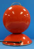
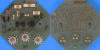
The Multiputer features a distinctive design consisting of two large hemispherical metal shells stacked on top of each other. The lower section houses the power supply, on/off switch, and keyboard, while the upper section contains the main electronics, including the LED display, happy and sad face indicators, rotary switches, reset button, and carrying handle.
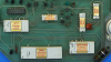
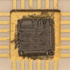
 Dismantling the
Multiputer CPD-15 manufactured in November 1973 in New Mexico, USA by Omni
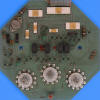
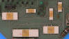
Corporation, reveals a relatively simple design with extensive hand-soldering, necessitated by the lack of through-hole plating in the double-sided printed circuit board (PCB). The power supply located in the lower housing section employs extensive flying-wire connections and interfaces with the Main-PCB in the upper section through a three-wire connection, while the keyboard unit is attached using a hand-soldered flat ribbon cable.
Dismantling the
Multiputer CPD-15 manufactured in November 1973 in New Mexico, USA by Omni
Corporation, reveals a relatively simple design with extensive hand-soldering, necessitated by the lack of through-hole plating in the double-sided printed circuit board (PCB). The power supply located in the lower housing section employs extensive flying-wire connections and interfaces with the Main-PCB in the upper section through a three-wire connection, while the keyboard unit is attached using a hand-soldered flat ribbon cable.
 We borrowed this Multiputer CPD-15 educational computer in
May 2026 (Thanks to Jeri) not only to better understand the innovative PPS 25 Building Blocks, but also to explore the evolutionary path that ultimately led to Texas Instruments' Little Professor. To gain some knowledge about the PPS 25 design used with the Multiputer, we decided here at the Datamath Calculator Museum to give it a "Teardown Treatment" and share our findings accordingly.
We borrowed this Multiputer CPD-15 educational computer in
May 2026 (Thanks to Jeri) not only to better understand the innovative PPS 25 Building Blocks, but also to explore the evolutionary path that ultimately led to Texas Instruments' Little Professor. To gain some knowledge about the PPS 25 design used with the Multiputer, we decided here at the Datamath Calculator Museum to give it a "Teardown Treatment" and share our findings accordingly.
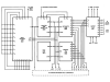
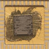
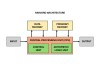 Microprocessor System: A minimal PPS 25 design uses six Integrated Circuits interconnected by 4-bit data buses and various control signals, corresponding directly to the block diagram of a computer based on the Harvard architecture. At the core of the system is the CPU, composed of the
3805 Arithmetic/Logic Unit and the
3806 Control Unit. The
3808 and 3809 Data Memories each provide three dynamic 25-digit shift registers, while the 3810 Program Memory provides 256 12 bits of storage. The
3803 and 3807 Input chips support up to 32 keys and 16 switches each, and the
3811 Output chip drives displays of up to 16 digits. The clock frequency of
the PPS 25 Building Blocks is 400 kHz, resulting in a Digit Time of 2.5 us and a Word Time of 62.5 us.
The Multiputer CPD-15 manufactured in November 1973 is using as expected six PPS 25 Building Blocks on its large double-sided PCB:
Microprocessor System: A minimal PPS 25 design uses six Integrated Circuits interconnected by 4-bit data buses and various control signals, corresponding directly to the block diagram of a computer based on the Harvard architecture. At the core of the system is the CPU, composed of the
3805 Arithmetic/Logic Unit and the
3806 Control Unit. The
3808 and 3809 Data Memories each provide three dynamic 25-digit shift registers, while the 3810 Program Memory provides 256 12 bits of storage. The
3803 and 3807 Input chips support up to 32 keys and 16 switches each, and the
3811 Output chip drives displays of up to 16 digits. The clock frequency of
the PPS 25 Building Blocks is 400 kHz, resulting in a Digit Time of 2.5 us and a Word Time of 62.5 us.
The Multiputer CPD-15 manufactured in November 1973 is using as expected six PPS 25 Building Blocks on its large double-sided PCB:
|
3805 Arithmetic Chip Contains the Adder/Subtractor and the 25-digit BCD Register A 3806 (SL30342) Function and Timing Unit Contains Program Counter, Branch Logic, 2 25-bit Status Registers and generates the Master timing 3807 Input Device Scans the keyboard and rotary switches 3809 Memory Register Contains three 25-digit BCD Register E, F, and G 3810 (SL30745) ROM Contains the Micro Instructions of the PPS 25 System with 256 x 12 bits 3811 Output Device Stores the BCD data of the 7-segment display and the LED indicators and provides multiplexing of the display |
The PPS 25 System is supported by some additional SSI (Small Scale Integration) and MSI (Medium Scale Integration) chips in TTL (Transistor-Transistor Technology), for segment decoding of the BCD data for the 7-segment display and some housekeeping logic.
Display: The featured Multiputer CPD-15 manufactured in November 1973 utilizes four Litronix DL707 LED seven-segment displays along with three discrete LEDs used to indicate the selected math function and equal sign. Small masks with cutouts for the addition, multiplication, and equal sign symbols are mounted on the red protective screen directly in front of these LEDs. The happy-face and sad-face "emojis" are represented by slightly larger masks on the same protective screen and are illuminated by two low-voltage incandescent lamps.
Keyboard and Switches: Located in the lower half of the Multiputer CPD-15, the 11-key keyboard module connects to the Main-PCB through a 16-pin cable. The 3807 Input Device generates a unique 5-bit code for every key press and release, while also monitoring the three rotary switches responsible for selecting difficulty level, math topic, and session length.
Clock: The PPS 25 System is using a 2-phase, non-overlapping clock for its dynamic and static logic with a large voltage swing between VSS and VGG. The featured Multiputer CPD-15 manufactured in November 1973 is using a clock oscillator with discrete transistors and additional level shifters to accommodate the PPS 25 requirements. We measured a clock frequency of 140 kHz with the evaluated device.
Power Supply: Located in the lower portion of the Multiputer CPD-15 is a center-tapped transformer, paired with a two-diode rectifier and filter capacitors to create a full-wave DC supply of roughly 17 volts. On the Main-PCB, a three-terminal linear regulator provides a stable +5V output for the PPS 25 Building Blocks VSS rail, the TTL logic devices, and the LED displays. The negative PPS 25 Building Blocks VGG supply of -9.5V is generated through a Zener diode and transistor regulator circuit.
 A
Main-PCB of a Mathiputer CPD-35 manufactured in October 1975 was donated to the Datamath Calculator Museum (Thanks to Jeri) for the sole purpose of decapping its six Building Blocks and we added the
die photos to their respective Datasheets.
A
Main-PCB of a Mathiputer CPD-35 manufactured in October 1975 was donated to the Datamath Calculator Museum (Thanks to Jeri) for the sole purpose of decapping its six Building Blocks and we added the
die photos to their respective Datasheets.
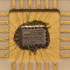
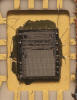
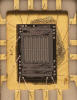
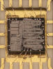 Die photos courtesy of Sean Riddle.
CPD-15 Operation and Logic Implementation
The Multiputer Computational Skill Trainer CPD-15 employs a range of controls, indicators, and digital displays for user interaction.
The base of the CPD-15 houses the power switch and an 11-key keyboard used for numerical entry, along with an Execute key. The upper control panel contains three 4-position rotary switches for selecting the difficulty level, math topic, and session length, as well as a push button used to start a teaching session. The control panel display consists of seven indicators and five seven-segment LED displays arranged in three groups.
Controls
[POWER] On/Off switch, right side of CPD-15 base.
11-key Keyboard, front side of CPD-15 base:
|
• [0]...[9] – Numerical input for 1-digit or 2-digit numbers • [EXC] Execute – Request next quiz of current session |
[NUMBER GROUP] 4-position rotary switch, CPD-15 control panel, left position. Each quiz generated by the CPD-15 uses two random numbers based on the selected math topic. The [NUMBER GROUP] switch determines the set of possible random numbers used for the first addend or first factor, which is shown in the first seven-segment display field:
|
• '0-3' – Only numbers between 0 and 3 are used for first addend or first factor • '4-6' – Only numbers between 0 and 3 are used for used for first addend or first factor • '7-9' – Only numbers between 0 and 3 are used for used for first addend or first factor • '0-9' – All numbers between 0 and 9 are used for used for first addend or first factor |
[MODE] 4-position rotary switch, CPD-15 control panel, center position. The CPD-15 provided math quizzes to train addition and multiplication. Depending on the selected math topic and difficulty level, the possible number range of the second addend, sum, second factor, or product is chosen. The table below is based on the [NUMBER GROUP] switch set to '0-9':
|
• '+ ADD' – Second addend 0-9
for sums of 0-18: X + Y = ? • '− SUB' – Sum 0-18 and larger or equal to first addend: X + ? = Z • '× MULT' – First factor 0-9 for products of 0-81: X × Y = ? • '÷ DIV' – Product 0-81 for a second factor of 0-9: X × ? = Z |
[NUMBER OF PROBLEMS] 4-position rotary switch, CPD-15 control panel, right position. The number of quizzes per teaching session can be set to 10, 25, 50, or 100:
|
• '10' – Grading of the teaching session after 10 quizzes • '25' – Grading of the teaching session after 25 quizzes • '50' – Grading of the teaching session after 50 quizzes • '100' – Grading of the teaching session after 100 quizzes |
[START] The red push button below the [MODE] rotary switch is used to initiate a teaching session. Any changes made to the positions of the 4-position rotary switches are registered only after the [START] button is pressed. Otherwise, the CPD-15 may exhibit erratic behavior..
Indicators and Digital Readouts
The visual feedback of the CPD-15 is provided by various indicators and digital readouts arranged in seven groups and covered by a red acrylic display bezel. Their functionality, from left to the right, is provided with the following table:
|
• WRONG • 8 1-digit 7-segment display – Displays the first addend or first factor during a quiz • + × – One of two indicators showing the selected math topic • 8 1-digit 7-segment display – Displays the second addend, entered addend, or second factor, or entered factor during a quiz. Showing for '− SUB' and '÷ DIV' the correct answer if a wrong answer is entered • = – Indicator for the equal sign, always on during quizzes, off at the end of a teaching session • 88 2-digit 7-segment display – Displays the entered sum, sum, entered product, or product if a correct answer is entered. Showing for '+ ADD' and '× MULT' the correct answer if a wrong answer is entered • RIGHT |
Operation
Operation of the Multiputer Computational Skill Trainer CPD-15 consists of three steps:
|
• 1 – Configuration of the teaching session • 2 – Answering the quizzes presented during the session • 3 – Grading of the teaching session |
The configuration of a teaching session is carried out with the three 4-position rotary switches to select the difficulty level [NUMBER GROUP], math topic [MODE], and session length [NUMBER OF PROBLEMS] and confirming the selections with the red push button [START].
Example: [NUMBER GROUP] = '0-9', [MODE] = '− SUB', and [NUMBER OF PROBLEMS] = '10'.
After pressing [START], the CPD-15 is configured and the display would show in its seven groups:
| + | = |
The student begins the teaching session by pressing the [EXC] key, after which the CPD-15 presents the first of ten quizzes:
| 5 | + | = | 8 |
If the student enters the correct answer [3] with the numeric keypad, the result appears in the answer field and the RIGHT indicator illuminates:
| 5 | + | 3 | = | 8 | RIGHT |
Pressing the [EXC] key again presents the second quiz:
| 1 | + | = | 7 |
If the student enters a wrong answer [5], the correct answer is shown but the WRONG indicator illuminates:
| WRONG |
1 | + | 6 | = | 7 |
Entering an incorrect answer locks the numeric keypad, and the [EXC] key must be pressed again. The CPD-15 then presents the same quiz again:
| 1 | + | = | 7 |
These steps are repeated until all quizzes in the teaching session have been answered correctly.
The CPD-15 is then grading the finished teaching session with showing the number of correct answers in the display:
| 9 |
If the student answers all questions correctly, the RIGHT indicator also illuminates:
| 10 | RIGHT |
Random Number Generation
Both the CPD-35 and CPD-15 are generating two Random Numbers R1 and R2 that are used for the math quizzes. The number range of R1 is fixed:
|
• R1 ∈ (0,1,2,3,4,5,6,7,8,9) |
The number range of R2 depends from the setting of the [RANGE] or [NUMBER GROUP] 4-position rotary switch:
|
• '0-3' – R2 ∈ (0,1,2,3) • '4-6' – R2 ∈ (4,5,6) • '7-9' – R2 ∈ (7,8,9) • '0-9' – R2 ∈ (0,1,2,3,4,5,6,7,8,9) |
The two Random Numbers R1 abd R2 are independent of each other.
Logic Implementation
Although the quizzes presented by the CPD-35 and CPD-15 are completely different, are they running essentially the same software on their underlying Fairchild PPS 25 Processor System.
With the [MODE] switch set to '− SUB', the CPD-35 is actually performing the addition of R1 and R2 and then showing the sum of R1 + R2 as minuend and R2 as subtrahend, expecting the student to enter R1 as difference while the CPD-15 is showing R2 as first addend, the sum of R1 and R2 as sum, expecting the student to enter R1 as second addend.
With the [MODE] switch set to '÷ DIV', the CPD-35 is actually performing the multiplication of R1 and R2 and then showing the product of R1 × R2 as dividend and R2 as divisor, expecting the student to enter R1 as quotient while the CPD-15 is showing R2 as dividend, the product of R1 and R2 as product, expecting the student to enter R1 as divisor:
| [MODE] Switch |
CPD-35 Quiz |
CPD-15 Quiz |
| '+ ADD' | R1 + R2 = ? | R2 + R1 = ? |
| '− SUB' | (R1+R2) − R2 = ? | R2 + ? = (R1+R2) |
| '× MULT' | R1 × R2 = ? | R2 × R1 = ? |
| '÷ DIV' | (R1×R2) ÷ R2 = ? | R2 × ? = (R1×R2) |
Known Bugs
Changing the [MODE] switch during a teaching session may result in unexpected quiz behavior.
If you have additions to the above article please email: joerg@datamath.org.
Joerg Woerner, May 23, 2026. No reprints without written permission.