DATAMATH CALCULATOR MUSEUM
|
|
DATAMATH CALCULATOR MUSEUM |
Characterization of Single-chip Calculator Circuits - TMS0600 Product Family
The DCM-50A Platform supports the Characterization of TMS0600 Devices in its leftmost TMS0100 Textool Test Socket with the voltages VSS set to 7.2V and VGG set to -7.2V, accordingly.

![]() Device-under-Test:
Device-under-Test:
| • Package Markings Top: TMS0601NC,
DP7439 • Package Markings Bottom: DP0601DP • Donor Calculator: TI-2550, October 1975 |
Keyboard: The TI-2550 makes use of a 1KS 146 keyboard assembly with 23 Klixon™ hermetic snap action switches mounted on a printed circuit board (PCB) and arranged in a 10*3 matrix with the rows connected to the D1-D11 Outputs (Display Scan) and the columns connected to the KN (Keyboard Scan Numerical), KO (Keyboard Scan Operational) and KQ (Keyboard Scan Constant) Inputs of the TMS0601NC single-chip calculator circuit. The [F 2 4] switch to select Floating or Fixed Decimal Point operation is connected between the D2 and D4 Outputs and the KP (Keyboard Scan Decimal Point) Input.
Keyboard Matrix of the TI-2550:
TMS0601 |
||||
| KN | KO | KP | KQ | |
| D1 | 1 | + | ||
| D2 | 2 | × | [F 2] | |
| D3 | 3 | ÷ | ||
| D4 | 4 | − | [F 4] | M− |
| D5 | 5 | % | ||
| D6 | 6 | M+ | ||
| D7 | 7 | = | ||
| D8 | 8 | CE | MR | |
| D9 | 9 | . | ||
| D10 | 0 | C | CM | |
| D11 | ||||
![]() Display:
The TI-2550 (PCB Type 2 and Display Type 3) makes use of a DIS206C Nine-Digit Calculator Numeric
Seven-Segment LED Display module.
Display:
The TI-2550 (PCB Type 2 and Display Type 3) makes use of a DIS206C Nine-Digit Calculator Numeric
Seven-Segment LED Display module.
Display Layout:
| Texas Instruments DIS206C |
|
|
Display Layout:
The Digit Outputs D11 (leftmost Digit) to D1 (right most Digit) of the TMS0601NC are not connected directly to the physical Digit positions of the DIS206C Nine-Digit Calculator Numeric Seven-Segment displays:
| TMS0601 Pin | 13 | 12 | 11 | 10 | 9 | 8 | 7 | 6 | 5 | 4 | 3 |
| TMS0601 Port | D11 | D10 | D9 | D8 | D7 | D6 | D5 | D4 | D3 | D2 | D1 |
| Digit Position | D9 | D8 | D7 | D6 | D5 | D4 | D3 | D2 | D1 |
Note: The TMS0601 chip outputs in the unused Digit Positions D2 the position of the decimal point and D1 the value of most-significant digit of the number stored in the Memory.
The Output Decoder PLA of the TMS0601NC is programmed for 7-Segment displays with the following Output Assignments:
| TMS0601 Pin | 16 | 17 | 18 | 19 | 20 | 21 | 22 | 23 | 24 |
| TMS0601 Port | SA | SB | SC | SD | SE | SF | SG | SH | SP |
| Segment | A | B | C | D | E | F | G | DP |
| The Segment drivers A-G and DP (Decimal Point) are connected to the DIS206C display in the pictured way. | 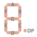 |
Display Fonts:
| Type | Calculator | Number Fonts | Decimal Separator |
Entry Overflow |
Calculating Overflow |
Memory Overflow |
Segment H | Memory Indicator |
| TMS0601NC | TI-2550 |
|
Note: The DIS206C Display module has Segment B, Segment C and the Decimal Point (Segment DP) of the leftmost digit not bonded out, changing the appearance of the Calculating Overflow, Memory Overflow and Memory Indicators accordingly.

 Scanning: Display and keyboard scanning is performed in D11 → D1 direction at a rate of about
584 Hz without the Digit- and Segment-Blanking:
Scanning: Display and keyboard scanning is performed in D11 → D1 direction at a rate of about
584 Hz without the Digit- and Segment-Blanking:
|
• State Time = 3 Clocks =
0.012 ms @ CK=250 kHz • Digit Time = 13 States (1 Instruction Cycle) = 0.156 ms @ CK=250 kHz • Scan Time = 11 Digit Times (D1 to D11) = 1.712 ms @ CK=250 kHz |

![]() Device-under-Test:
Device-under-Test:
| • Package Markings Top:
TMS0602NC, B7441 • Package Markings Bottom: D0602DP • Donor Calculator: SR-11, November 1974 |
Keyboard: The SR-11 makes use of a 3KS 103 keyboard assembly with 24 Klixon™ hermetic snap action switches mounted on a printed circuit board (PCB) and arranged in an 11*3 matrix with the rows connected to the D1-D11 Outputs (Display Scan) and the columns connected to the KN (Keyboard Scan Numerical), KO (Keyboard Scan Operational) and KP (Keyboard Scan Decimal Point) Inputs of the TMS0602NC single-chip calculator circuit. The [K] switch to select the Constant Mode is connected between the D10 Output and the KQ (Keyboard Scan Constant) Input.
Keyboard Matrix of the SR-11:
TMS0602 |
||||
| KN | KO | KP | KQ | |
| D1 | 9 | − | ||
| D2 | 8 | + | ||
| D3 | 7 | × | ||
| D4 | 6 | ÷ | ||
| D5 | 5 | CD | ||
| D6 | 4 | EE | √x | |
| D7 | 3 | +/− | ||
| D8 | 2 | = | 1/x | |
| D9 | 1 | . | ||
| D10 | 0 | PI | x2 | [- K] |
| D11 | C | |||
![]() Display:
The SR-11 (Version 2) makes use of twelve DISXXX Seven-Segment displays soldered
onto a small DIS005G Display-PCB.
Display:
The SR-11 (Version 2) makes use of twelve DISXXX Seven-Segment displays soldered
onto a small DIS005G Display-PCB.
Display Layout:
| Texas Instruments DIS005G |
|
|
Display Layout:
The Digit Outputs D11 (leftmost Digit) to D1 (right most Digit) of the TMS0602NC are not connected directly to the physical Digit positions of the DIS005G Twelve-Digit Calculator Numeric Seven-Segment display module:
| TMS0602 Pin | 13 | 12 | 11 | 10 | 9 | 8 | 7 | 6 | 5 | 4 | 3 |
| TMS0602 Port | D11 | D10 | D9 | D8 | D7 | D6 | D5 | D4 | D3 | D2 | D1 |
| Digit Position | D12 | D11 | D10 | D9 | D8 | D7 | D6 | D5 | D4 | D2 | D1 |
Note: The TMS0602 chip outputs in the Digit Positions D11 with Segment H the minus sign of the Exponent (D3).
The Output Decoder PLA of the TMS0602NC is programmed for 7-Segment displays with the following Output Assignments:
| TMS0602 Pin | 16 | 17 | 18 | 19 | 20 | 21 | 22 | 23 | 24 |
| TMS0602 Port | SA | SB | SC | SD | SE | SF | SG | SH | SP |
| Segment | A | B | C | D | E | F | G | (G) | DP |
| The Segment drivers A-G/H and DP (Decimal Point) are connected to the DIS005G display in the pictured way. The TMS0602 repurposes the Segment H for the minus sign of the Exponent in the pictured way. | 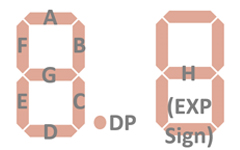 |
Display Fonts:
| Type | Calculator | Number Fonts | Decimal Separator |
Entry Overflow |
Calculating Overflow |
Memory Overflow |
Segment H | Memory Indicator |
| TMS0602NC | SR-11 |
|

 Scanning: Display and keyboard scanning is performed in D11 → D1 direction at a rate of about
584 Hz without the Digit- and Segment-Blanking:
Scanning: Display and keyboard scanning is performed in D11 → D1 direction at a rate of about
584 Hz without the Digit- and Segment-Blanking:
|
• State Time = 3 Clocks =
0.012 ms @ CK=250 kHz • Digit Time = 13 States (1 Instruction Cycle) = 0.156 ms @ CK=250 kHz • Scan Time = 11 Digit Times (D1 to D11) = 1.712 ms @ CK=250 kHz |

![]() Device-under-Test:
Device-under-Test:
| • Package Markings Top: TMS0603NCΔ, B7433 • Package Markings Bottom: JX0603B 33 • Donor Calculator: Brother Model 827R (Version 2), September 1974 |
Keyboard: The Brother Model 827R (Version 2) makes use of a keyboard assembled with individual long-stroke push-button switches arranged in an 11*3 matrix with the rows connected to the D1-D11 Outputs (Display Scan) and the columns connected to the KN (Keyboard Scan Numerical), KO (Keyboard Scan Operational) and KQ (Keyboard Scan Constant) Inputs of the TMS0603NC single-chip calculator circuit. The [∑] switch to activate the Auto-Summation feature is connected between the D11 Output and the KP (Keyboard Scan Decimal Point) Input.
Keyboard Matrix of the Brother Model 827R (Version 2):
TMS0603 |
||||
| KN | KO | KP | KQ | |
| D1 | 1 | + | ||
| D2 | 2 | × | ||
| D3 | 3 | ÷ | ||
| D4 | 4 | − | ||
| D5 | 5 | M+ | ||
| D6 | 6 | M− | CM | |
| D7 | 7 | RM | ||
| D8 | 8 | = | C | |
| D9 | 9 | . | ||
| D10 | 0 | |||
| D11 | [ - ∑] | % | ||
![]() Display: The
Brother Model 827R (Version 2) makes use of a Hewlett-Packard HP1130-0513
Nine-Digit Calculator Numeric Seven-Segment LED Display module with a discrete
LED for the Memory Indicator.
Display: The
Brother Model 827R (Version 2) makes use of a Hewlett-Packard HP1130-0513
Nine-Digit Calculator Numeric Seven-Segment LED Display module with a discrete
LED for the Memory Indicator.
Display Layout:
| Hewlett-Packard HP1130-0513 plus LED |
|
|
The Digit Outputs D11 (leftmost Digit) to D1 (right most Digit) of the TMS0603NC are not connected directly to the physical Digit positions of the HP1130-0513 Display module:
| TMS0603 Pin | 13 | 12 | 11 | 10 | 9 | 8 | 7 | 6 | 5 | 4 | 3 |
| TMS0603 Port | D11 | D10 | D9 | D8 | D7 | D6 | D5 | D4 | D3 | D2 | D1 |
| Digit Position | D9 | D8 | D7 | D6 | D5 | D4 | D3 | D2 | D1 |
Note: The TMS0603 chip outputs in the unused Digit Positions D2 the position of the decimal point and D1 the value of Digit 7 of the number stored in the Memory.
The Output Decoder PLA of the TMS0603NC is programmed for 7-Segment displays with the following Output Assignments:
| TMS0603 Pin | 16 | 17 | 18 | 19 | 20 | 21 | 22 | 23 | 24 |
| TMS0603 Port | SA | SB | SC | SD | SE | SF | SG | SH | SP |
| Segment | A | B | C | D | E | F | G | DP |
| The Segment drivers A-G and DP (Decimal Point) are connected to the HP1130-0513 display in the pictured way. Segment H is connected at Digit Time D8 with the Memory Indicator LED. | |
Display Fonts:
| Type | Calculator | Number Fonts | Decimal Separator |
Entry Overflow |
Calculating Overflow |
Memory Overflow |
Segment H | Memory Indicator |
| TMS0603NC | Brother Model 827R |
Status | Seg. H (D8) |

 Flag-Information:
The TMS0603 is outputting on its Segment H Output the status of internal
internal Flags during the Digit Times D1 to D11 that can be used for external Indicator
LEDs and and debug purposes:
Flag-Information:
The TMS0603 is outputting on its Segment H Output the status of internal
internal Flags during the Digit Times D1 to D11 that can be used for external Indicator
LEDs and and debug purposes:
| • D1 - D4: Operation with
D1 = M, D1 + D3 = D, D2 = A, D2 + D4 = S • D5: Automatic Constant • D6: Floating Calculation • D7: Not used • D8: Memory Indicator • D9: Memory Overflow Indicator • D10: Calculating Overflow Indicator • D11: Sign |

 Scanning: Display and keyboard scanning is performed in D11 → D1 direction at a rate of about
584 Hz with the Digits and Segments blanked at State S1 and State S13:
Scanning: Display and keyboard scanning is performed in D11 → D1 direction at a rate of about
584 Hz with the Digits and Segments blanked at State S1 and State S13:
|
• State Time = 3 Clocks =
0.012 ms @ CK=250 kHz • Digit Time = 13 States (1 Instruction Cycle) = 0.156 ms @ CK=250 kHz • Scan Time = 11 Digit Times (D1 to D11) = 1.712 ms @ CK=250 kHz |

![]() Device-under-Test:
Device-under-Test:
| • Package Markings Top: TMS0604NC, B7430 • Package Markings Bottom: J0604BP • Donor Calculator: Dittel TMP608, August 1974 |
Keyboard: The Dittel TMP608 makes use of a keyboard with 23 snap action switches arranged in an 11*3 matrix with the rows connected to the D1-D11 Outputs (Display Scan) and the columns connected to the KN (Keyboard Scan Numerical), KO (Keyboard Scan Operational) and KP (Keyboard Scan Decimal Point) Inputs of the TMS0604NC single-chip calculator circuit. The [∑] switch to activate the Auto-Summation feature is connected between the D3 Output and the KQ (Keyboard Scan Constant) Input and the [K] switch to activate the Constant Mode is connected between D10 and KQ.
Keyboard Matrix of the Dittel TMP608:
TMS0604 |
||||
| KN | KO | KP | KQ | |
| D1 | 1 | S | ||
| D2 | 2 | × | ||
| D3 | 3 | ÷ | [ - ∑] | |
| D4 | 4 | += | ||
| D5 | 5 | −= | ||
| D6 | 6 | M+= | T | |
| D7 | 7 | M−= | ||
| D8 | 8 | % | CM | |
| D9 | 9 | . | ||
| D10 | 0 | C/CE | [ - K] | |
| D11 | CA | |||
![]() Display: The
Dittel TMP608 makes use of three Litronix DL330 Three-Digit Calculator Numeric Seven-Segment LED Display modules.
Display: The
Dittel TMP608 makes use of three Litronix DL330 Three-Digit Calculator Numeric Seven-Segment LED Display modules.
Display Layout:
| 3 Litronix DL330 Modules |
|
|
The Digit Outputs D11 (leftmost Digit) to D1 (right most Digit) of the TMS0604NC are not connected directly to the physical Digit positions of the Litronix DL330 Display modules:
| TMS0604 Pin | 13 | 12 | 11 | 10 | 9 | 8 | 7 | 6 | 5 | 4 | 3 |
| TMS0604 Port | D11 | D10 | D9 | D8 | D7 | D6 | D5 | D4 | D3 | D2 | D1 |
| Digit Position | D9 | D8 | D7 | D6 | D5 | D4 | D3 | D2 | D1 |
Note: The TMS0604 chip outputs in the unused Digit Positions D2 the position of the decimal point and D1 the value of Digit 8 of the number stored in the Memory.
The Output Decoder PLA of the TMS0604NC is programmed for 7-Segment displays with the following Output Assignments:
| TMS0604 Pin | 16 | 17 | 18 | 19 | 20 | 21 | 22 | 23 | 24 |
| TMS0604 Port | SA | SB | SC | SD | SE | SF | SG | SH | SP |
| Segment | A | B | C | D | E | F | G | DP |
| The Segment drivers A-G and DP (Decimal Point) are connected to the 3*DL330 display in the pictured way. | |
Display Fonts:
| Type | Calculator | Number Fonts | Decimal Separator |
Entry Overflow |
Calculating Overflow |
Memory Overflow |
Segment H | Memory Indicator |
| TMS0604NC | Dittel TMP608 |
Status | Seg. H (D8) |

 Flag-Information:
The TMS0604 is outputting on its Segment H Output the status of internal
internal Flags during the Digit Times D1 to D11 that can be used for external Indicator
LEDs and and debug purposes:
Flag-Information:
The TMS0604 is outputting on its Segment H Output the status of internal
internal Flags during the Digit Times D1 to D11 that can be used for external Indicator
LEDs and and debug purposes:
| • D1: C/CE Flag • D2 - D4: Operation with D4 + D2 = M, D4 + D3 + D2 = D, D2 = A and S • D5: Not used • D6: T Function • D7: % Function • D8: Memory Indicator • D9: Memory Overflow Indicator • D10: Calculating Overflow Indicator • D11: Sign |

 Scanning: Display and keyboard scanning is performed in D11 → D1 direction at a rate of about
584 Hz with the Digits and Segments blanked at State S1 and State S13:
Scanning: Display and keyboard scanning is performed in D11 → D1 direction at a rate of about
584 Hz with the Digits and Segments blanked at State S1 and State S13:
|
• State Time = 3 Clocks =
0.012 ms @ CK=250 kHz • Digit Time = 13 States (1 Instruction Cycle) = 0.156 ms @ CK=250 kHz • Scan Time = 11 Digit Times (D1 to D11) = 1.712 ms @ CK=250 kHz |

![]() Device-under-Test:
Device-under-Test:
| • Package Markings Top: TMC0605NCΔ,
A7423 • Package Markings Bottom: JX0605A 23 • Donor Calculator: Canon LE-81M, June 1974 |
Keyboard: The keyboard assembly of the Canon LE-81M uses spring-supported plastic keys pushing a small conductive rubber element against two contacts etched on a single-sided phenolic PCB combining both long-travel keys with reasonable manufacturing costs while maintaining longevity of the calculator. The keyboard module is connected with a short 20-pin flat-cable to the Main-PC. The switches are arranged in a 10*3 matrix with the rows connected to the D1-D10 Outputs (Display Scan) and the columns connected to the KN (Keyboard Scan Numerical), KO (Keyboard Scan Operational) and KP (Keyboard Scan Decimal Point) Inputs of the TMC0605NC single-chip calculator circuit. The [AM] switch to activate the Auto-Summation feature is connected between the D14 Output and the KQ (Keyboard Scan Constant) Input.
Keyboard Matrix of the Canon LE-81M:
TMC0605 |
||||
| KN | KO | KP | KQ | |
| D1 | 1 | + | ||
| D2 | 2 | × | ||
| D3 | 3 | ÷ | ||
| D4 | 4 | − | [ - AM] | |
| D5 | 5 | = | ||
| D6 | 6 | √x | ||
| D7 | 7 | T | ||
| D8 | 8 | %± | ||
| D9 | 9 | . | C | |
| D10 | 0 | CE | ||
| D11 | ||||
![]() Display: The
Canon LE-81M makes use of a Bowmar Optostic R7H-122-9 Nine-Digit display module using Chip-on-Board (COB) technology with each character formed by bonding seven individual Segment chips and one Comma chip bonded directly to a PCB and protected with a red plastic lens. The display module is connected with a long 17-pin flat-cable to the Main-PCB.
Display: The
Canon LE-81M makes use of a Bowmar Optostic R7H-122-9 Nine-Digit display module using Chip-on-Board (COB) technology with each character formed by bonding seven individual Segment chips and one Comma chip bonded directly to a PCB and protected with a red plastic lens. The display module is connected with a long 17-pin flat-cable to the Main-PCB.
Display Layout:
| Bowmar Optostic R7H-122-9 |
|
|
The Digit Outputs D11 (leftmost Digit) to D1 (right most Digit) of the TMC0605NC are not connected directly to the physical Digit positions of the Bowmar Optostic R7H-122-9 Display module:
| TMC0605 Pin | 13 | 12 | 11 | 10 | 9 | 8 | 7 | 6 | 5 | 4 | 3 |
| TMC0605 Port | D11 | D10 | D9 | D8 | D7 | D6 | D5 | D4 | D3 | D2 | D1 |
| Digit Position | D9 | D8 | D7 | D6 | D5 | D4 | D3 | D2 | D1 |
Note: The TMC0605 chip outputs in the unused Digit Positions D2 the position of the decimal point and D1 the value of Digit 8 of the number stored in the Memory.
The Output Decoder PLA of the TMC0605NC is programmed for 7-Segment displays with the following Output Assignments:
| TMC0605 Pin | 16 | 17 | 18 | 19 | 20 | 21 | 22 | 23 | 24 |
| TMC0605 Port | SA | SB | SC | SD | SE | SF | SG | SH | SP |
| Segment | A | B | C | D | E | F | G | DP |
| The Segment drivers A-G and DP (Decimal Point) are connected to the Bowmar Optostic R7H-122-9 display in the pictured way. | |
Display Fonts:
| Type | Calculator | Number Fonts | Decimal Separator |
Entry Overflow |
Calculating Overflow |
Memory Overflow |
Segment H | Memory Indicator |
| TMC0605NC | Canon LE-81M |
|
Status | Seg. H (D8) |

 Flag-Information:
The TMC0605 is outputting on its Segment H Output the status of internal
internal Flags during the Digit Times D1 to D11 that can be used for external Indicator
LEDs and and debug purposes:
Flag-Information:
The TMC0605 is outputting on its Segment H Output the status of internal
internal Flags during the Digit Times D1 to D11 that can be used for external Indicator
LEDs and and debug purposes:
| • D1: Not used • D2 - D4: Operation with D4 + D2 = M, D4 + D3 + D2 = D, D2 = A and S • D5: Not used • D6: Not used • D7: Memory Overflow Indicator • D8: Memory Indicator • D9: Not used • D10: Calculating Overflow Indicator • D11: Sign |

 Scanning: Display and keyboard scanning is performed in D11 → D1 direction at a rate of about
584 Hz with the Digits blanked at State S1 and State S13 but no Segment
blanking:
Scanning: Display and keyboard scanning is performed in D11 → D1 direction at a rate of about
584 Hz with the Digits blanked at State S1 and State S13 but no Segment
blanking:
|
• State Time = 3 Clocks =
0.012 ms @ CK=250 kHz • Digit Time = 13 States (1 Instruction Cycle) = 0.156 ms @ CK=250 kHz • Scan Time = 11 Digit Times (D1 to D11) = 1.712 ms @ CK=250 kHz |

![]() Device-under-Test:
Device-under-Test:
| • Package Markings Top: TMS0611NCΔ, B7439 • Package Markings Bottom: JX0611B 48 • Donor Calculator: Craig Model 4518, October 1974 |
Keyboard: The Craig Model 4518 makes use of a keyboard with individual long-stroke push-button switches arranged in an 11*3 matrix with the rows connected to the D1-D11 Outputs (Display Scan) and the columns connected to the KN (Keyboard Scan Numerical), KO (Keyboard Scan Operational) and KP (Keyboard Scan Decimal Point) Inputs of the TMS0611NC single-chip calculator circuit.
Keyboard Matrix of the Craig Model 4518:
TMS0611 |
||||
| KN | KO | KP | KQ | |
| D1 | 1 | + | ||
| D2 | 2 | × | ||
| D3 | 3 | ÷ | ||
| D4 | 4 | − | ||
| D5 | 5 | M+ | ||
| D6 | 6 | M− | ||
| D7 | 7 | √x | ||
| D8 | 8 | = | % | |
| D9 | 9 | . | ||
| D10 | 0 | CE | T | |
| D11 | C | |||
![]() Display: The
Craig Model 4518 makes use of nine Fairchild FND357 Seven-Segment displays
soldered onto a small Display-PCB.
Display: The
Craig Model 4518 makes use of nine Fairchild FND357 Seven-Segment displays
soldered onto a small Display-PCB.
Display Layout:
| 9 Fairchild FND357 Displays |
|
|
The Digit Outputs D11 (leftmost Digit) to D1 (right most Digit) of the TMS0611NC are not connected directly to the physical Digit positions of the nine Fairchild FND357 Seven-Segment displays:
| TMS0611 Pin | 13 | 12 | 11 | 10 | 9 | 8 | 7 | 6 | 5 | 4 | 3 |
| TMS0611 Port | D11 | D10 | D9 | D8 | D7 | D6 | D5 | D4 | D3 | D2 | D1 |
| Digit Position | D9 | D8 | D7 | D6 | D5 | D4 | D3 | D2 | D1 |
Note: The TMS0611 chip outputs in the unused Digit Positions D2 the position of the decimal point and D1 the value of Digit 8 of the number stored in the Memory.
The Output Decoder PLA of the TMS0611NC is programmed for 7-Segment displays with the following Output Assignments:
| TMS0611 Pin | 16 | 17 | 18 | 19 | 20 | 21 | 22 | 23 | 24 |
| TMS0611 Port | SA | SB | SC | SD | SE | SF | SG | SH | SP |
| Segment | A | B | C | D | E | F | G | DP |
| The Segment drivers A-G and DP (Decimal Point) are connected to the 9*FND357 display in the pictured way. | 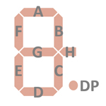 |
Display Fonts:
| Type | Calculator | Number Fonts | Decimal Separator |
Entry Overflow |
Calculating Overflow |
Memory Overflow |
Segment H | Memory |
| TMS0611NC | Craig Model 4518 |
|
Note: The display of the Craig Model 4518 calculator does not use Segment H.

 Scanning: Display and keyboard scanning is performed in D11 → D1 direction at a rate of about
584 Hz with the Digits and Segments blanked at State S1 and State S13:
Scanning: Display and keyboard scanning is performed in D11 → D1 direction at a rate of about
584 Hz with the Digits and Segments blanked at State S1 and State S13:
|
• State Time = 3 Clocks =
0.012 ms @ CK=250 kHz • Digit Time = 13 States (1 Instruction Cycle) = 0.156 ms @ CK=250 kHz • Scan Time = 11 Digit Times (D1 to D11) = 1.712 ms @ CK=250 kHz |
If you have additions to the above article please email: joerg@datamath.org.
© Joerg Woerner, December 21, 2024. No reprints without written permission.